trinityamps.com

Trinity Amps Guitar Amp Forum
It is currently Sat Nov 23, 2024 4:31 am

All times are UTC - 5 hours [ DST ]


Post new topic Reply to topic  [ 54 posts ]  Go to page 1, 2, 3  Next
Author Message
PostPosted: Thu Feb 18, 2016 9:16 pm 
Offline
Friend
Friend

Joined: Fri Feb 05, 2016 8:39 pm
Posts: 41
Just began the heater wiring and the boss shows up for an inspection!
Image
Image

Heater inspiration photo in the background credit to cigarman.


Top
 Profile  
 
PostPosted: Fri Feb 19, 2016 11:24 am 
Offline
Holy Ghost
Holy Ghost
User avatar

Joined: Sun Mar 13, 2005 4:10 pm
Posts: 7519
Location: Canada
Nice. Great view you have there too!!

_________________
Stephen
Web: www.trinityamps.com. Facebook: facebook.com/trinityamps. Twitter: @trinityamps


Top
 Profile  
 
PostPosted: Fri Feb 19, 2016 4:33 pm 
Offline
Friend
Friend

Joined: Fri Feb 05, 2016 8:39 pm
Posts: 41
To back up a bit - super exciting project for me; first amp build! First Trinity in Alaska?

The box! Much smaller than I expected.
Image

How it's all packed - very impressive.
Image

It's all beautifully bagged and organized.
Image

Bill of Materials checked out perfectly, down to the washer.
Image


Top
 Profile  
 
PostPosted: Fri Feb 19, 2016 6:08 pm 
Offline
Holy Ghost
Holy Ghost
User avatar

Joined: Sun Mar 13, 2005 4:10 pm
Posts: 7519
Location: Canada
The next box will be bigger!

_________________
Stephen
Web: www.trinityamps.com. Facebook: facebook.com/trinityamps. Twitter: @trinityamps


Top
 Profile  
 
PostPosted: Fri Feb 19, 2016 7:32 pm 
Offline
Expert
Expert
User avatar

Joined: Sun Feb 17, 2008 4:47 pm
Posts: 960
Location: Toronto, Canada.
Great looking workshop

_________________
http://pdfelectronics.com


Top
 Profile  
 
PostPosted: Fri Feb 19, 2016 9:33 pm 
Offline
Friend
Friend

Joined: Fri Feb 05, 2016 8:39 pm
Posts: 41
kurtlives wrote:
Great looking workshop

Well, I wish I could keep a neater workspace... :)
Also, kurtlives, your custom build detailed in these pages is a big inspiration for me to reach toward.
This is my first amp build; I've done a lot of work on my old Fender, Valco and Magnatone amps, and built a lot of pedals kit and scratch, but this is a much bigger scale.

As a hobbyist I don't have a dedicated space to store or work on this stuff, so I have to pull it all out and throw it together when a project arrives. Got in the habit of taping off this Styrofoam tray and writing all the resistor values with a sharpie and then stick the right resistors in the right place. Handles BOM inventory and then easier to grab the right ones when I need 'em. Obviously not a production shop solution but great for the weekend warrior with limited space.
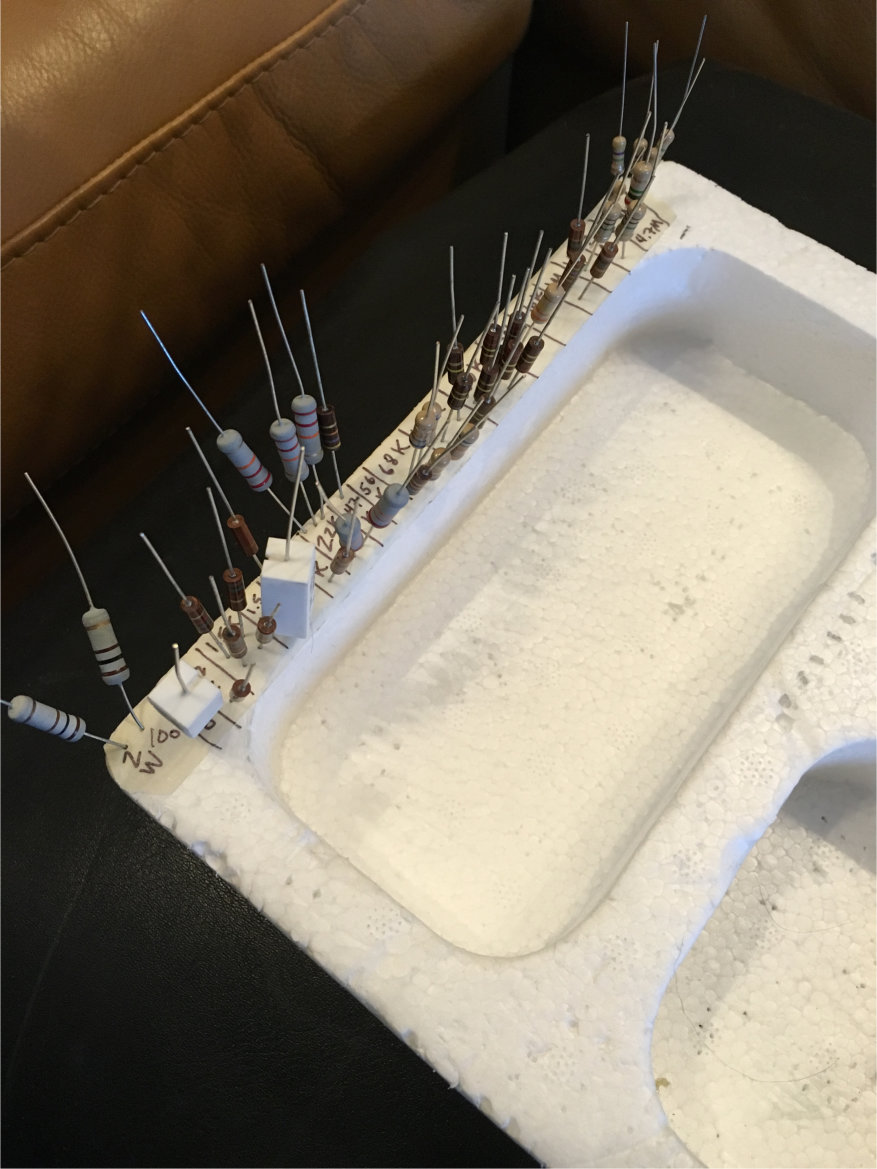
Image

Styro works for me because even in the little bins you can stick the leads in the walls to keep them sorted.
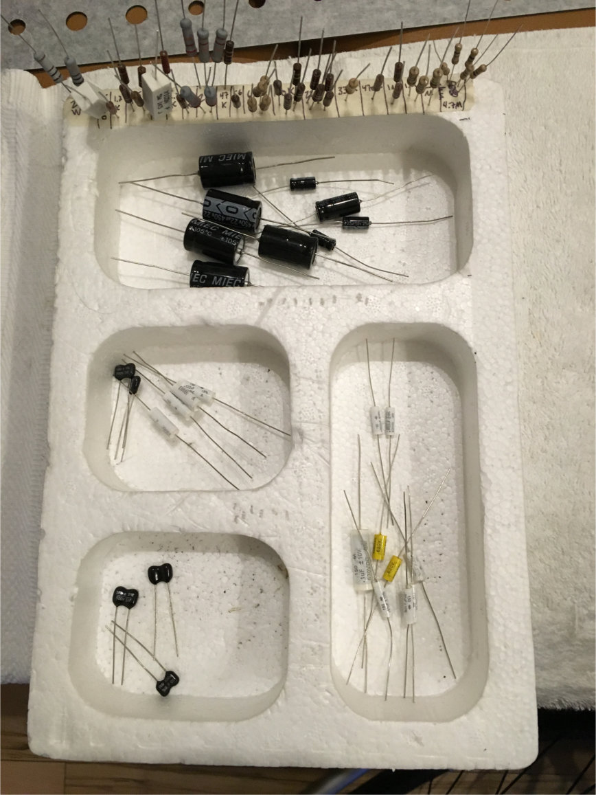
Image

Got all the hardware on and checked out.
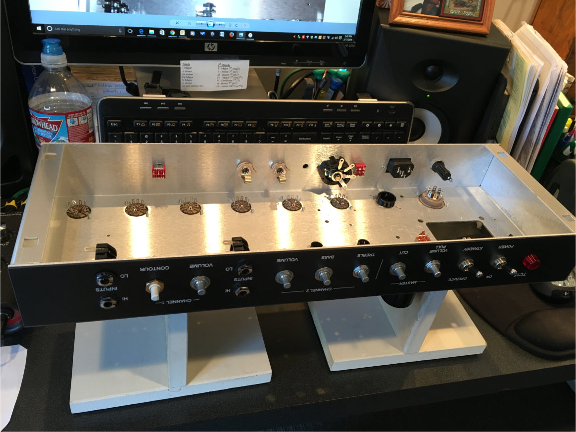
Image

Years ago I was lusting after a real amp chassis cradle, but too cheap, etc. so I whipped up these simple "T" dealies out of 5/8" MDF. Rubber feet top and bottom so everything stays in place. They're actually pretty handy as they are so 'adjustable' and can be placed any way needed. Probably nowhere as handy without the angle feature of a real chassis cradle but better than putting the chassis on my lap like I used to!
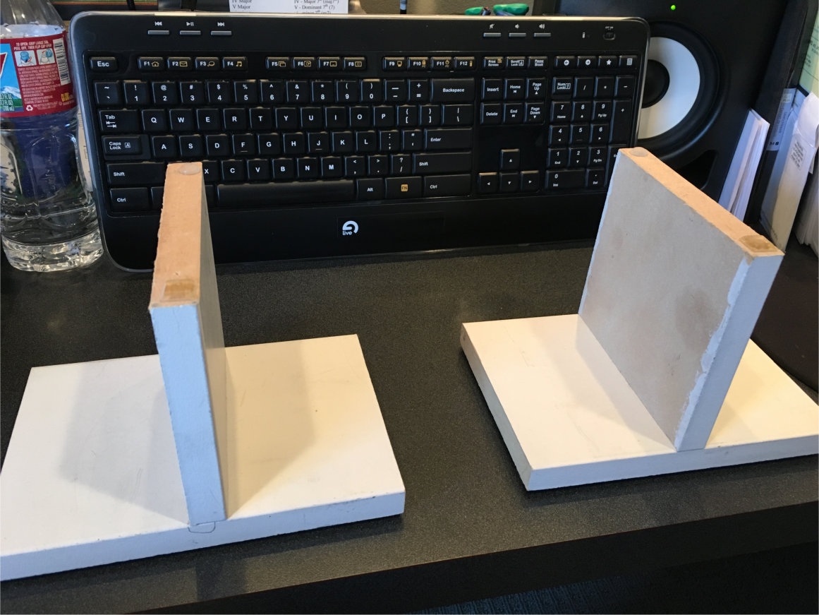
Image


Last edited by 2x6L6 on Sun Feb 21, 2016 5:32 pm, edited 2 times in total.

Top
 Profile  
 
PostPosted: Fri Feb 19, 2016 11:36 pm 
Offline
Holy Ghost
Holy Ghost
User avatar

Joined: Sun Mar 13, 2005 4:10 pm
Posts: 7519
Location: Canada
Looking very organized. That's good!

_________________
Stephen
Web: www.trinityamps.com. Facebook: facebook.com/trinityamps. Twitter: @trinityamps


Top
 Profile  
 
PostPosted: Sat Feb 20, 2016 5:39 am 
Offline
Friend
Friend

Joined: Fri Feb 05, 2016 8:39 pm
Posts: 41
Speaking of heater wiring - got that knocked out last night. Way trickier than I thought, but eventually got in the groove.
Image

Off to a reasonably good start but as I got warmed up and back in the groove I realized I had to re-do V6, as I wasn't watching my dwell and melted the insulation. Necessitated a removal, trim-back ad had to add some heat-shrink to the black to square it away. Much better.
Image

All in all I'm pretty pleased so far.
Image

And now with the heater wiring done, on to installing the transformers. It's starting to look (and feel) like an amp! Sorry about the mess...
Image

Next up: learning to braid 4-strands. BTW, any and all comments, constructive criticism, advice is greatly appreciated, as this is my first build and I'm doing my best to follow the directions and mimic the fine build threads on the forum here - but have no real idea if I am meeting with success (yet). Thanks in advance!


Top
 Profile  
 
PostPosted: Sat Feb 20, 2016 10:13 am 
Offline
Expert
Expert
User avatar

Joined: Sun Feb 17, 2008 4:47 pm
Posts: 960
Location: Toronto, Canada.
If you are referring to the OT braiding most people braid the 4/8/16 and leave the 0 (common). The 0 goes a different place than the other wires anyways so it doesn't make much sense to braid it.

_________________
http://pdfelectronics.com


Top
 Profile  
 
PostPosted: Sat Feb 20, 2016 1:50 pm 
Offline
Experienced
Experienced
User avatar

Joined: Tue Mar 25, 2014 3:55 pm
Posts: 214
Location: Central California
Looking good!

Palmer, AK.... I love Alaska. One of my favorite places on the planet. Been there five times now. Want to go back!


Top
 Profile  
 
PostPosted: Sat Feb 20, 2016 6:47 pm 
Offline
Friend
Friend

Joined: Fri Feb 05, 2016 8:39 pm
Posts: 41
kurtlives wrote:
If you are referring to the OT braiding most people braid the 4/8/16 and leave the 0 (common). The 0 goes a different place than the other wires anyways so it doesn't make much sense to braid it.

Oops - guess I should have read ahead more closely, as this is how I spent a BUNCH of time yesterday.... oh, well! Learned a new skill.

Image

Image


Top
 Profile  
 
PostPosted: Sat Feb 20, 2016 10:59 pm 
Offline
Expert
Expert

Joined: Sat Dec 04, 2010 3:42 pm
Posts: 519
Location: Qualicum Beach, BC
Great looking build so far. You can't be too neat when it comes to wiring and keeping the insulation good as close to the joint as possible. It can be tricky some times to do that without melting the insulation.

Good organization, too. I never thought of using styrofoam and masking tape to keep the resistors sorted and handy during a build. You learn something new every day!

Nice wire braiding. I have never tried doing that. I usually use cable lacing to keep transformer and ac wires under control. Something like this:

Attachment:
SELchassis1.jpg
SELchassis1.jpg [ 291.14 KiB | Viewed 27906 times ]


It's not my TC-15, it's an amp I built later but it shows the technique. You can also use nylon cable ties and that's what I did on my TC-15.

Nice moose, too. It looks pretty cold there in Alaska. I lived in the Yukon for a couple of years so I'm well acquainted with cold winter weather and the beauty of the North. I have visited Alaska and I would love to go back some time.


Top
 Profile  
 
PostPosted: Sat Feb 20, 2016 11:09 pm 
Offline
Friend
Friend

Joined: Fri Feb 05, 2016 8:39 pm
Posts: 41
I got the braiding from cigarman's TC15 build. I REALLY like the tight zip tie approach. Really nice and neat.


Top
 Profile  
 
PostPosted: Sun Feb 21, 2016 12:16 am 
Offline
Holy Ghost
Holy Ghost
User avatar

Joined: Sun Mar 13, 2005 4:10 pm
Posts: 7519
Location: Canada
All looking good. I likre to braid as there is more noise cancellation.

_________________
Stephen
Web: www.trinityamps.com. Facebook: facebook.com/trinityamps. Twitter: @trinityamps


Top
 Profile  
 
PostPosted: Sun Feb 21, 2016 3:14 am 
Offline
Friend
Friend

Joined: Fri Feb 05, 2016 8:39 pm
Posts: 41
Just about finished the power supply last night. Progress pics:

Image

Don't think I ever would have figured out the blue/white twist without cigarman's detailed photos.

Image

Getting close here:

Image

Bit of a discrepancy in the directions on the rectifier wiring. The manual says to hook the white and the yellow 6.3 VAC to pins 8 and 2 on the rectifier, and to connect the unused yellow 6.3 VAC to the terminal strip. However, the unused wire is white, and two heater wires are yellow and yellow/white, according to the layout drawing and other threads I see here. So, hopefully I've done this right, even though it isn't what the direction say.

Image

Sculpting these wires is a blast - just wish I could get them to behave and sit perfectly square and flush!

Image

Hoping to finish the power supply tonight so I can get after some voltage testing - big milestone!!


Top
 Profile  
 
PostPosted: Sun Feb 21, 2016 9:05 am 
Offline
Holy Ghost
Holy Ghost
User avatar

Joined: Sun Mar 13, 2005 4:10 pm
Posts: 7519
Location: Canada
Remember when you tirn it on with no load, the voltage levels will be much higher.

_________________
Stephen
Web: www.trinityamps.com. Facebook: facebook.com/trinityamps. Twitter: @trinityamps


Top
 Profile  
 
PostPosted: Sun Feb 21, 2016 4:18 pm 
Offline
Friend
Friend

Joined: Fri Feb 05, 2016 8:39 pm
Posts: 41
Stephen - the rectifier wiring is OK?
Also - why is it safe to plug it in with no speaker load at this point?


Top
 Profile  
 
PostPosted: Sun Feb 21, 2016 10:53 pm 
Offline
Expert
Expert
User avatar

Joined: Sun Feb 17, 2008 4:47 pm
Posts: 960
Location: Toronto, Canada.
You haven't hooked up the OT.

even if you did there is no signal going into it.

_________________
http://pdfelectronics.com


Top
 Profile  
 
PostPosted: Sun Feb 21, 2016 11:55 pm 
Offline
Friend
Friend

Joined: Fri Feb 05, 2016 8:39 pm
Posts: 41
kurtlives wrote:
You haven't hooked up the OT.

even if you did there is no signal going into it.

Makes sense. And I am moments away from OT hookup!


Top
 Profile  
 
PostPosted: Mon Feb 22, 2016 12:36 am 
Offline
Expert
Expert

Joined: Sat Dec 04, 2010 3:42 pm
Posts: 519
Location: Qualicum Beach, BC
Your rectifier wiring is fine. Actually it looks really good! Not easy to keep all those flexible wires looking as neat as you got them. The solid wires connecting the tubes, pots and switches will be a lot easier to manage.

You can test the AC and the rectifier now but you will only get pulsating DC out of the rectifier until the main filter capacitor is connected. You can check the high voltage AC going to the rectifier but any DC voltage readings on the rectifier output will be irrelevant at this stage.


Top
 Profile  
 
Display posts from previous:  Sort by  
Post new topic Reply to topic  [ 54 posts ]  Go to page 1, 2, 3  Next

All times are UTC - 5 hours [ DST ]


Who is online

Users browsing this forum: No registered users and 47 guests


You cannot post new topics in this forum
You cannot reply to topics in this forum
You cannot edit your posts in this forum
You cannot delete your posts in this forum
You cannot post attachments in this forum

Search for:
Jump to:  
Powered by phpBB® Forum Software © phpBB Group