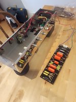
Hi all ! Little followup and a batch of questions... I saw that a resitor was missing so I had to wait to get it to continue. In the meantime I've started the build of the cabinet (cf. last pictures below). So as I said I have few questions. I've tried to find answers on my own but still I'd need some explaination. Hopefully it will be ok for you guys. I realize I have many...
 - Resitors :
 the one missing was a 56K. I've received it today and checked with my multimeter and it appears it's 52.4 (instead of 56k +/-5% it should be between 53,4 and 58,8).
Is it still acceptable even it's above the 5% tolerance ? The other ones seem to be ok (with the +/-5%) except the 220K. One is 211 and the other one 233.
- Signal wires : it is said in the first step that "it's imperative that where possible, the signal wires run close to the chassis, while the heater wires run as far away from the signal wires". I recognize now what's the heater wires but what are the signal wires exactly : all the others that are not heater wires or few of them (and if so wich ones ?) I wondering because I want to know for the installation of the flying leads... (if they are signal wires, I will install them as close to the chassis as possible, otherwise I won't care).
-
Yellow wires (twisted from the board) : (cf. pciture below..) Do I use the big heat shrink for this wires ? I may have missed the info but I don't see the use of it anywhere in the documentation. The 2 others (the small and medium ones are for the co-axial cable, aren't they ?)
Attachment:
 12.jpg [ 358.55 KiB | Viewed 26777 times ]
Attachment:
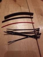 14.jpg [ 273.34 KiB | Viewed 26777 times ]
- Optionnal 470K cathodyne : Is the 470K resistor optionnal or also the yellow wire itself is also optionnal ? +it's optionnal, ok... but what the difference with or without ??
Attachment:
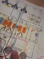 11_470koption.jpg [ 333.25 KiB | Viewed 26777 times ]
- Co-axial calbe : from the points 3 to 5 of the following pic, I'm completely lost about what I'm supposed to do... I don't know if it's because english is not my first language but I cannot figure out this part. Also I don't understand why there's this mention "be sure to ground only at this end of the cable". The other end of the co-axial cable is not connected to anything, right ?
Attachment:
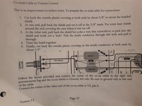 13.jpg [ 367.59 KiB | Viewed 26777 times ]
- Last one (sorry... sigh...) VRM : with the installation of the VRM, the yellow wires have to be connected only to the eyelet I marked as 1 on the picture (not to the one I marked as 2, isn't it ?)
Attachment:
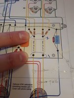 10vrm.jpg [ 268.14 KiB | Viewed 26777 times ]
Also, If someone can provide a picture of his/her VRM installation (this current version), it would be appreciated. Obviously, there's something I definitely don't get here... If I follow the instructions as I see them, there's no way it would fit as is. The mosfet is supposed to be located on the side of the green paper I've put (I don't want to use it for now and risk to damage it since I've no clue how to use/place the potentiometer yet).
Attachment:
 09VRM.jpg [ 259.86 KiB | Viewed 26777 times ]
So here are my questions, Hopefully there're not to many at a time...

After this batch I think I'll be all good to finish the build.
THANKS A LOT !!!
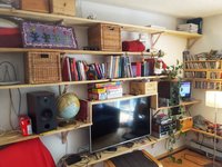
In the meantime, I've converted some solid raw pine shelves I use at home and started to build the cabinet (get the right thickness, dimension then find a way to do the 1/4 inches fingerjoints). So here I am...
Attachment:
 15etageres.jpg [ 435.43 KiB | Viewed 26777 times ]
Attachment:
 16cabinet.jpg [ 191.62 KiB | Viewed 26777 times ]
Attachment:
 17.jpg [ 260.8 KiB | Viewed 26777 times ]


