|
I’ve just started putting my kit together and have a power switch question. When installing the power switch, there is an obvious groove on the threads and a little tooth on the case that forces the switch to go in only one way. Seems like a great way to keep us newby’s from messing it up. The question I have is that when I install the switch, the lugs to solder to are pointing deep into the case and hard to get to. When I see pictures from other builds, the lugs are pointing out of the case and easier to access. When I flip the switch as it is installed, there is continuity when the switch is pointed in the “off” position and no continuity when switched to the “on” position. Am I overthinking this, or should it be the other way around?
| Attachments: |
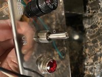
0946E43E-DF95-4316-9EAE-B8C7F8DC230D.jpeg [ 2.92 MiB | Viewed 10534 times ]
|
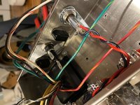
E69B5AAA-19FF-4C37-BD07-0C78760165ED.jpeg [ 3 MiB | Viewed 10534 times ]
|
|

