trinityamps.com

Trinity Amps Guitar Amp Forum
It is currently Thu Jul 18, 2024 10:19 am

All times are UTC - 5 hours [ DST ]


Post new topic Reply to topic  [ 10 posts ] 
Author Message
 Post subject: Channel Switching
PostPosted: Tue Mar 28, 2006 9:48 am 
Offline
Holy Ghost
Holy Ghost
User avatar

Joined: Sun Mar 13, 2005 4:10 pm
Posts: 7519
Location: Canada
For those who have built in one of these, do you have a good schematic/layout for one? I'm looking for one that doesn't pop, is relaiable, uses easy to get parts and works of the 6.3V heater voltage.

Maybe even an A-B-Y switcher?

_________________
Stephen
Web: www.trinityamps.com. Facebook: facebook.com/trinityamps. Twitter: @trinityamps


Top
 Profile  
 
 Post subject:
PostPosted: Tue Mar 28, 2006 3:26 pm 
Offline
Novice
Novice
User avatar

Joined: Sat Apr 02, 2005 10:32 am
Posts: 122
Location: JAX, FL
I do these all the time. I'll have to come up with a good schematic. I'll also see what relay I ordered from Mouser last time, but I've done this with a few different relays. I generally use the 6.3 fillament voltage tap, unless there's another 5 or 6.3V tap not being used.

The trick to the pop is how you switch and where you put the switching.

What amp are you trying to add switching to?

I'll see if I can get something together for you tonight.

_________________
Richard Johnson
-------------------
Playing an insturment doesn't make you a musician, listening does


Top
 Profile  
 
 Post subject:
PostPosted: Tue Mar 28, 2006 5:28 pm 
Offline
Holy Ghost
Holy Ghost
User avatar

Joined: Sun Mar 13, 2005 4:10 pm
Posts: 7519
Location: Canada
I got a request for it on an sIII (18W). I'd appreciate your help. I could always use a BBQ one I guess.

_________________
Stephen
Web: www.trinityamps.com. Facebook: facebook.com/trinityamps. Twitter: @trinityamps


Top
 Profile  
 
 Post subject:
PostPosted: Tue Mar 28, 2006 11:54 pm 
Offline
Novice
Novice
User avatar

Joined: Sat Apr 02, 2005 10:32 am
Posts: 122
Location: JAX, FL
Check your email

_________________
Richard Johnson
-------------------
Playing an insturment doesn't make you a musician, listening does


Top
 Profile  
 
 Post subject:
PostPosted: Wed Mar 29, 2006 9:07 am 
Offline
Holy Ghost
Holy Ghost
User avatar

Joined: Sun Mar 13, 2005 4:10 pm
Posts: 7519
Location: Canada
Here's rgtr's input. I'll post the schematic soon.

rjgtr wrote:
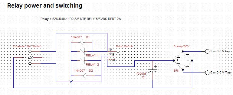
Here's the switching schematic. It only shows the power and relay coil sections. I also listed the Mouser part number of the relays. The schematic shows a three mode switching scheme. In my case it is Clean channel to Gain channel, then Gain mode one to gain mode two. For a simple two channel switching scheme leave out one of the relays.

Normally I use a combination of basic switching and grounding techniques. I'm usually doing switching with an amp that uses one input to the PI. So in the case of the sIII you could just use a SPDT relay, instead of the DPDT and just use grounding techniques. But I'd go ahead and get the DPDT anyway, just in case you need a little more control.

I generally ground the gain channel after the first or second gain stage. It all depends on the topology; in an amp that shares the first gain stage, I do the gain channel after the second gain stage. In the sIII, I'd just do it after the TMB's first stage. If that causes a pop then try moving it to the TMB master volume pot's input.

On the normal channel I'd ground from the volume control input.

The closer to the PI you get the less pop effect you're likely to get.

I'd also take one of the Normal channel inputs and wire it to feed both inputs, or add a switch. You could share the first gain stage but this would change the character of the amp.

_________________
Stephen
Web: www.trinityamps.com. Facebook: facebook.com/trinityamps. Twitter: @trinityamps


Top
 Profile  
 
 Post subject:
PostPosted: Wed Mar 29, 2006 9:08 am 
Offline
Holy Ghost
Holy Ghost
User avatar

Joined: Sun Mar 13, 2005 4:10 pm
Posts: 7519
Location: Canada
I was figuring to switch the inputs at V1. Will this incerease the 'pop potential' ?

I plan on retaining the current 4 inputs of the amp.

_________________
Stephen
Web: www.trinityamps.com. Facebook: facebook.com/trinityamps. Twitter: @trinityamps


Top
 Profile  
 
 Post subject:
PostPosted: Wed Mar 29, 2006 10:23 pm 
Offline
Holy Ghost
Holy Ghost
User avatar

Joined: Sun Mar 13, 2005 4:10 pm
Posts: 7519
Location: Canada
Schematic from rgtr:

Image

_________________
Stephen
Web: www.trinityamps.com. Facebook: facebook.com/trinityamps. Twitter: @trinityamps


Top
 Profile  
 
 Post subject:
PostPosted: Fri Mar 31, 2006 3:27 am 
Offline

Joined: Wed Mar 16, 2005 8:43 pm
Posts: 4
Location: Wichita KS. USA
D1 and D2 are backwards.


Top
 Profile  
 
 Post subject:
PostPosted: Fri Mar 31, 2006 7:37 am 
Offline
Holy Ghost
Holy Ghost
User avatar

Joined: Sun Mar 13, 2005 4:10 pm
Posts: 7519
Location: Canada
I'll have to get rgtr to change it.

BTW, has anyone used JFETs for switching? they would work instead of relays and no pop at all? - Thoughts?

_________________
Stephen
Web: www.trinityamps.com. Facebook: facebook.com/trinityamps. Twitter: @trinityamps


Top
 Profile  
 
 Post subject:
PostPosted: Sat Apr 01, 2006 11:23 pm 
Offline

Joined: Wed Mar 16, 2005 8:43 pm
Posts: 4
Location: Wichita KS. USA
I have thought about it. But I do my switching on both sides of the PI and have no noise so I thought why complicate it.


Top
 Profile  
 
Display posts from previous:  Sort by  
Post new topic Reply to topic  [ 10 posts ] 

All times are UTC - 5 hours [ DST ]


Who is online

Users browsing this forum: No registered users and 8 guests


You cannot post new topics in this forum
You cannot reply to topics in this forum
You cannot edit your posts in this forum
You cannot delete your posts in this forum
You cannot post attachments in this forum

Search for:
Jump to:  
Powered by phpBB® Forum Software © phpBB Group