Sorry I missed the conversation. The relay wiring and test procedure has been corrected pand updated and if you didn't get a notification, let me know.
Attachment:
 IMG_0423.JPG [ 2.17 MiB | Viewed 21794 times ]
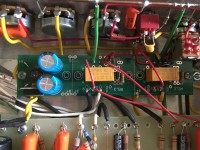
To Test the Overdrive RELAY Board
WITH NO TUBES INSTALLED
To test the RELAY board, you need to first confirm that
the PCB power supply is developing 5VDC.
Turn the power on and measure the DC voltage between
the PCB pad labelled B+ (this is not amp B+!)on the board
and the pad labelled G (ground) .
You should have measured 5VDC between the RELAY
board B+ and G (ground).
Apply 5VDC to each
RELAY coil by means
of small jumper. Run
the jumper between the
LED Cathode to the
ground bus to test.
When applied, the LED
should illuminate as you
energize each coil.
TIP: If you build the
Footswitch now, you can also test the RELAY board using
the footswitch.
https://www.dropbox.com/s/0ros8mhisbm22 ... d.pdf?dl=0


