trinityamps.com

Trinity Amps Guitar Amp Forum
It is currently Tue Jul 16, 2024 4:04 pm

All times are UTC - 5 hours [ DST ]


Post new topic Reply to topic  [ 5 posts ] 
Author Message
PostPosted: Sun Jul 15, 2012 8:05 pm 
Offline
Friend
Friend

Joined: Mon Apr 16, 2012 9:15 pm
Posts: 19
Hello again! I've just finished wiring up all the leads to/from the power transformer, mains, rectifier and the heater wiring. I'm at the point where the manual suggests plugging in and taking voltage measurements in order to verify against expected voltages (before any tubes, or even the board is connected). I clipped the black lead of my meter to the chassis and measured all voltages in AC. They are slightly off... is this to be expected?

Measured directly at the mains input, I am getting a solid 119v from the wall.

Wires from PT:
Red to Rect pin1 - Expected: 290v Measured: 316.8v
Red to Rect pin7 - Expected: 290v Measured: 316.8
White to Rect pin5 - Expected: 6.3v Measured: 3.59v
Yellow to Rect pin 4 - Expected: 0v Measured: .33v
Green to heaters - Expected: 3.15v Measured: 3.53v
Green to heaters - Expected: 3.15v Measured 3.53v

The red wires don't seem to be off by much (then again, I don't know how much is too much), but the white wire to pin 5 of the rectifier has me worried. Am I performing the measurements correctly?

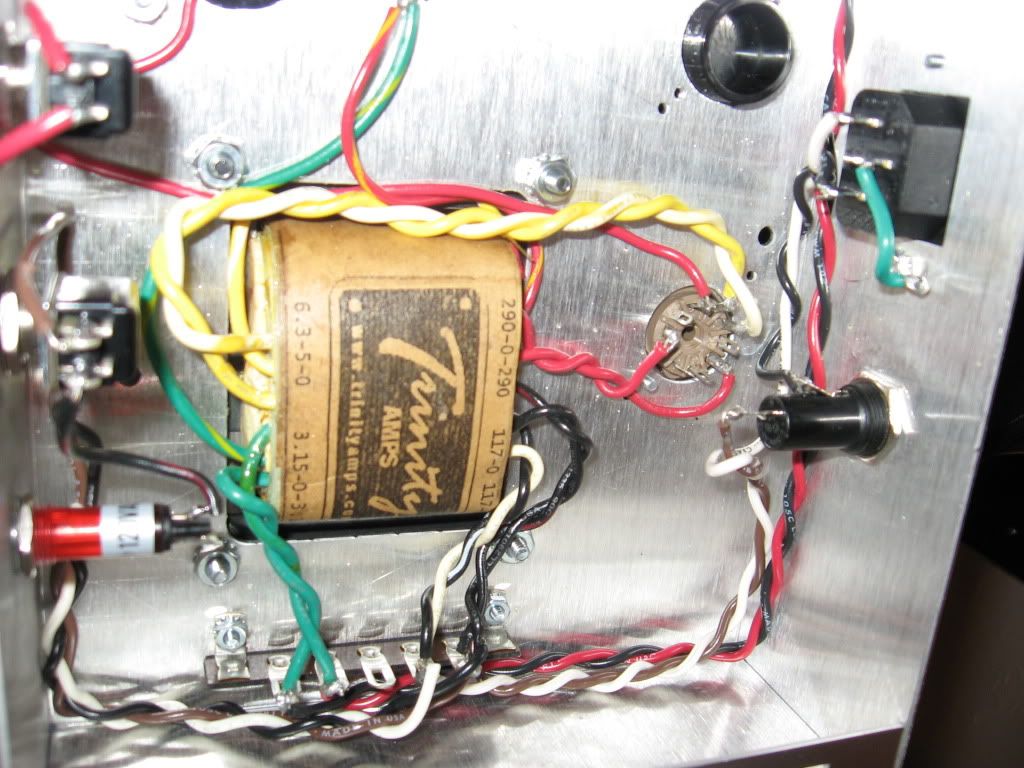
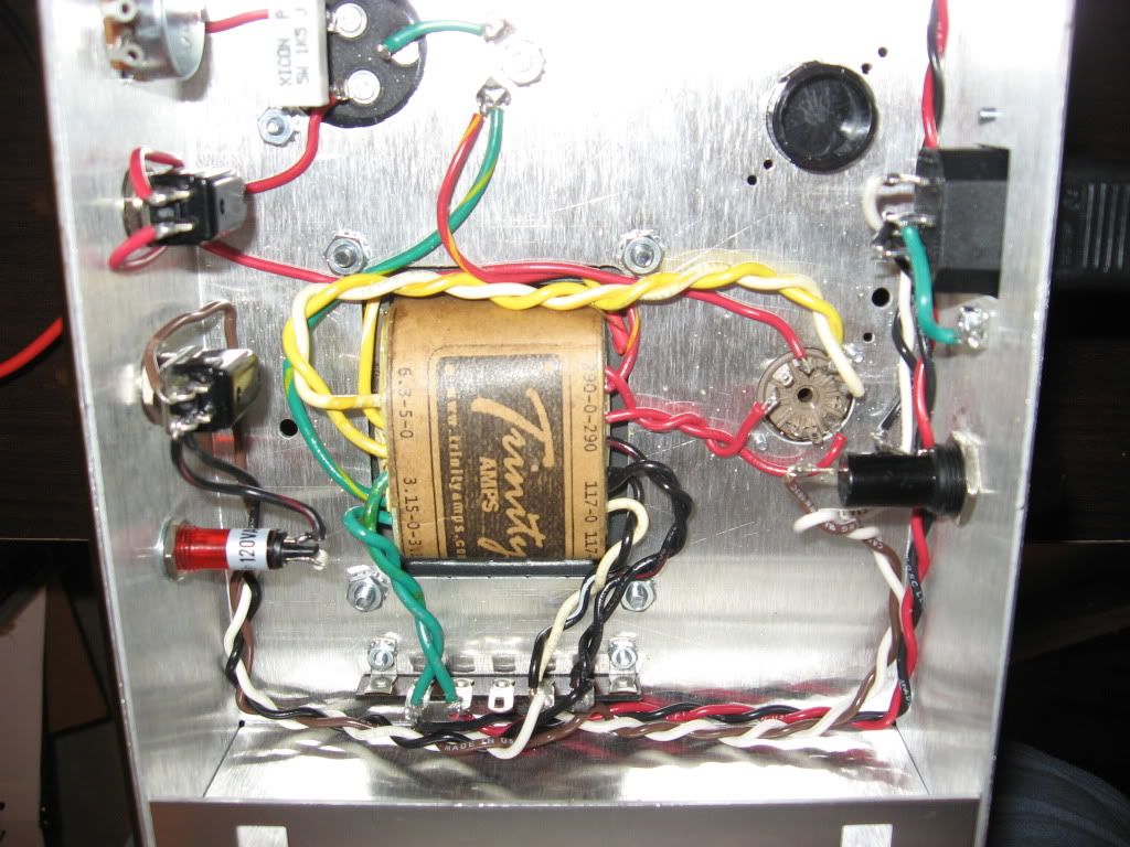
I have attached some photos just in case they are useful:

Image

Image


Top
 Profile  
 
PostPosted: Mon Jul 16, 2012 11:37 am 
Offline
Friend
Friend

Joined: Mon Apr 16, 2012 9:15 pm
Posts: 19
Ok, so after reading a couple more threads, I ended up taking the measurement across pins 4 and 5 instead of against chassis ground. Still, It measures a hot 7v.


Top
 Profile  
 
PostPosted: Mon Jul 16, 2012 11:50 am 
Offline
Expert
Expert
User avatar

Joined: Sun Feb 17, 2008 4:47 pm
Posts: 960
Location: Toronto, Canada.
The transformer primary is 117V AC. This accommodates the ranging output of the wall sockets in homes these days. Depending where you live, season and even time of the day the mains voltage varies. The range is usually 115V – 125V. The transformer is speced at 117V, so right in the middle to help accommodate for the ranging voltages. Your 119V is a bit above the 117V. That shouldn’t make a difference but I’d though I’d mention it.

Quote:
Red to Rect pin1 - Expected: 290v Measured: 316.8v
Red to Rect pin7 - Expected: 290v Measured: 316.8
This is fine. When you install all the tubes there will be a load present and the HV should drop to around 290V AC. If it’s a bit above 290V that’s ok. A bit of extra voltage isn’t a bad thing as long as bias and other limitations are taken into consideration. The HV winding pull’s roughly around 90mA-100mA.

Quote:
White to Rect pin5 - Expected: 6.3v Measured: 3.59v
Yellow to Rect pin 4 - Expected: 0v Measured: .33v
This winding of the power transformer does not have a center tap (CT) so measure this voltage from pin to pin. Put one probe of your DMM on pin 5 and the other probe on pin 4. The reading your getting now is not accurate and basically meaningless.

Quote:
Green to heaters - Expected: 3.15v Measured: 3.53v
Green to heaters - Expected: 3.15v Measured 3.53v
This is fine. Again the voltage will drop when load is present (tube’s heaters!). The winding has no load on it, once it see’s the 3A or so of heater elements it should drop.

_________________
http://pdfelectronics.com


Top
 Profile  
 
PostPosted: Mon Jul 16, 2012 3:11 pm 
Offline
Friend
Friend

Joined: Mon Apr 16, 2012 9:15 pm
Posts: 19
Alright, cool. I figured the voltages had some wiggle room, but was unsure of just how much is acceptable.

kurtlives wrote:
Quote:
White to Rect pin5 - Expected: 6.3v Measured: 3.59v
Yellow to Rect pin 4 - Expected: 0v Measured: .33v
This winding of the power transformer does not have a center tap (CT) so measure this voltage from pin to pin. Put one probe of your DMM on pin 5 and the other probe on pin 4. The reading your getting now is not accurate and basically meaningless.


I read some more threads and found another user who was advised to do exactly what you mention. When I measured across pins 4 and 5, I got a hot 7v... acceptable?

Thanks so much for your help!


Top
 Profile  
 
PostPosted: Mon Jul 16, 2012 3:23 pm 
Offline
Expert
Expert
User avatar

Joined: Sun Feb 17, 2008 4:47 pm
Posts: 960
Location: Toronto, Canada.
Ya you got some wiggle room for sure. Tube amps are by no means an exact science. Tube’s themselves are 20% tolerance devices; this should tell you just how precise tube amp are. So ya I wouldn’t worry too much about the voltages now. Check them again when the amp is up and running with tubes installed. Your final working voltages should be +-10-15% of what the layout/schem calls for.

Pins 4 to 5 should be 6.3V and you’re getting 7V so again that’s fine. That voltage will come down a bit when you install tubes. Even still it’s fine.

_________________
http://pdfelectronics.com


Top
 Profile  
 
Display posts from previous:  Sort by  
Post new topic Reply to topic  [ 5 posts ] 

All times are UTC - 5 hours [ DST ]


Who is online

Users browsing this forum: No registered users and 35 guests


You cannot post new topics in this forum
You cannot reply to topics in this forum
You cannot edit your posts in this forum
You cannot delete your posts in this forum
You cannot post attachments in this forum

Search for:
Jump to:  
Powered by phpBB® Forum Software © phpBB Group