trinityamps.com

Trinity Amps Guitar Amp Forum
It is currently Sun Jun 30, 2024 1:17 pm

All times are UTC - 5 hours [ DST ]


Post new topic Reply to topic  [ 53 posts ]  Go to page 1, 2, 3  Next
Author Message
PostPosted: Thu Aug 11, 2011 8:34 pm 
Offline
Experienced
Experienced
User avatar

Joined: Wed Mar 31, 2010 5:47 pm
Posts: 341
Location: Oceanside, CA
Day 1: Feb 5, 2011. Yes, it was THAT long ago. Got the kit weeks before, but too busy to do anything other than read the manual and scour the forums for a while. Eventually got cracking with the instructinos and mounted the tube sockets and did all the heater wiring (which is my least favorite part of an amp, FWIW). I think I then added the pots on the front before it got too late.

Pics were taken months later before I started day 2, but they are correct.

http://i842.photobucket.com/albums/zz34 ... y1Pic1.jpg

http://i842.photobucket.com/albums/zz34 ... y1Pic2.jpg

http://i842.photobucket.com/albums/zz34 ... y1Pic3.jpg

_________________
Go Buckeyes!


Last edited by RMosack on Sat Aug 20, 2011 6:58 pm, edited 2 times in total.

Top
 Profile  
 
 Post subject: Re: Build Thread
PostPosted: Thu Aug 11, 2011 8:40 pm 
Offline
Experienced
Experienced
User avatar

Joined: Wed Mar 31, 2010 5:47 pm
Posts: 341
Location: Oceanside, CA
Day 2: July 24, 2011. Yes, five months did go by. It's a long story... :oops:

1) Added all the remaining components to the exterior of the chassis, but not of them were wired yet. Some will obviously need to come back off to make wiring easier later, but I'm following the instructions.

2) Added all the components to the circuit board. I'm anally cautious (that sounds weird!), so I check each and every one with a meter before soldering. I just don't trust myself to simply read a label or the color stripes and not make a mistake. This makes for a tedious process, but it at least gives me piece of mind that I didn't do a bonehead move. I had some questions with regard to the components in the kit versus the layout in this thread http://www.trinityamps.com/phpbb/viewtopic.php?f=7&t=2989 These were answered the same day by G-log and zaphod, even though it was a Sunday evening. Awesome!

Here are some pics. For what it's worth, those are not burn marks on the back of the circuit board. I actually made some sharpie marks around the holes where those underneath wires go so that I wouldn't screw them up. :D

http://i842.photobucket.com/albums/zz34 ... y2Pic1.jpg

http://i842.photobucket.com/albums/zz34 ... y2Pic2.jpg

http://i842.photobucket.com/albums/zz34 ... y2Pic3.jpg

http://i842.photobucket.com/albums/zz34 ... y2Pic4.jpg

http://i842.photobucket.com/albums/zz34 ... y2Pic5.jpg

http://i842.photobucket.com/albums/zz34 ... y2Pic6.jpg

http://i842.photobucket.com/albums/zz34 ... y2Pic7.jpg

_________________
Go Buckeyes!


Last edited by RMosack on Wed Aug 17, 2011 2:27 pm, edited 1 time in total.

Top
 Profile  
 
 Post subject: Re: Build Thread
PostPosted: Thu Aug 11, 2011 8:44 pm 
Offline
Experienced
Experienced
User avatar

Joined: Wed Mar 31, 2010 5:47 pm
Posts: 341
Location: Oceanside, CA
Day 3: August 7, 2011 Had some time on another Sunday.

1) Pretty much wired up all the stuff for the power section end of the amp:
- power and standby switches
- indicator light
- IEC and fuse
- power ground
- rectifier tube socket
- all power transformer wires related to any of this stuff.

2) Had a little extra time, so I put the resistors on both little lug strips that go on v1. A little job, but saves some time later.

(pics go here - need to get these off the wife's iPod)

_________________
Go Buckeyes!


Last edited by RMosack on Wed Aug 17, 2011 2:41 pm, edited 1 time in total.

Top
 Profile  
 
 Post subject: Re: Build Thread
PostPosted: Thu Aug 11, 2011 8:54 pm 
Offline
Experienced
Experienced
User avatar

Joined: Wed Mar 31, 2010 5:47 pm
Posts: 341
Location: Oceanside, CA
Day 4: August 10, 2011

Some late night soldering. I decided to do all the flying leads that attach to the circuit board. I did my best to follow the color coding on the Trinity layout to save myself trouble later, but it's not really possible unless I ran to the store and bought more wire. I had to make an "executive decision". Layout showed the green, blue, yellow, orange and black in the kit, but also featured gray wire, a sort of brown wire and pink wire. I had to decide between the pink and the sort of brown which one I would assign to purple. Then I decided to use some of the different black wire (slightly different look to the insulation) to represent the gray. The pink was another stab at assigning another color. I may have botched this one since too many wires close to each other now have the same color. Oh well! I'll still check every single one before connecting later, so I could've done it in one color without too much trouble anyway.

That went on until well after midnight, so I had to stop after posting some more questions in another thread: viewtopic.php?f=7&t=3008 Thanks to kurtlives for answers early the next morning - which would be today.

At this point, I only have a few things under the board (output transformer wires) still before I start getting to the step where I mount the board and the thing starts to look like an amp! Of course, there'll be loads of stuff at the front and back yet to solder.

One minor problem is that the kit clearly doesn't have enough shielded wire. There seems to be the exact right amount for all the stuff going to v1, but the Gain pot to v2 seems to be an oversight. Even with the cable in a straight line, there's just not enough there. Need at least another foot. Emailed Trinity...

Here's one pic from this day's build, plus a couple clarification shots from the layout regarding those questions mentioned above.

http://i842.photobucket.com/albums/zz34 ... y4Pic1.jpg

http://i842.photobucket.com/albums/zz34 ... y4Pic2.jpg

http://i842.photobucket.com/albums/zz34 ... y4Pic3.jpg

_________________
Go Buckeyes!


Last edited by RMosack on Wed Aug 17, 2011 2:43 pm, edited 1 time in total.

Top
 Profile  
 
 Post subject: Re: Build Thread
PostPosted: Mon Aug 15, 2011 12:55 pm 
Offline
Experienced
Experienced
User avatar

Joined: Wed Mar 31, 2010 5:47 pm
Posts: 341
Location: Oceanside, CA
Day 5: August 14, 2011

First off, got a reply from Trinity over the weekend regarding the shielded cable. It ended up being a non-issue since I actually got a few feet of it from a co-worker of mine on Saturday the 13th. This guy is a tinkerer/builder/musician type. He invited a few of us over for a combination jam session and show and tell of various electronic projects. My Trinity was only up to Day 4 status, but it still got some oohs and aahs. Can't beat a cool kit!

Sat down yesterday, August 14 from basically 3pm to 11pm with a few breaks here and there (e.g. dinner). Ended up getting way more done than I initially expected. As usual, I basically followed the sequence laid out in the Trinity instructions.

I began by doing all the wires from the board to the tube side of the amp. This took a long time. It's not just the tube, but all those fun little extras like the boost and gain switches, plus the impedance switch. Nothing is hard, but a lot of solder joints to make and wires to make "just so". The three little things that cross the tube sockets (two wires and one resistor) are finger fumblers, but getting them just so pays off in the long run.

Made one glaring mistake that drove me nuts. There's a wire that goes from R9 to pin 3 of V2. In my zeal to make everything just right before doing the boost switch, I accidentally ran the wire to pin 3 of v3 instead. Of course, I snipped it to be just the right length for v3. Aargh! Too short for v2! Instead of desoldering the wire from UNDER THE BOARD, I simply made the executive decision to lenghten the wire with a little solder joint wrapped with heat shrink. Should be OK. Not the first mistake...

At this point, the entire back of the amp is wired except for the coax cables that will cross the whole shebang.

Since I completed the hurdle of the back of the amp, I got inspired to tackled the control side too after a dinner break. Barring one more silly mistake, everthing except the four input jacks is done. I even ran the one coax wire from the Gain pot back to v2.

Speaking of mistakes, another wire length issue. For the most part, I used the instruction guideline of 9" or lead wires as a max guideline. Where applicable, I made some shorter given the short run to the components. But the wire that goes from the .022uF cap to the wiper of the Middle pot wasn't long enough. That baby needs to be almost a foot. Once again, I did the same thing as before. I lengthened and covered with heat shrink. Should be OK.

At this point, all I need to do before testing is
- wire up all four input jacks,
- solder the preamp ground (two wires from input jacks and one from board)
- run four coax cables to v1.
That's it! My kit is missing one of the 1M pots, so this was a good stopping point anyway. I'll just find a local pot and then get to work.

Nearing the home stretch!

Here are the pics I added. Note the weirdness in the boost switch wiring. I had made a minor mistake on one side of the switch. In lieu of desoldering one wire and/or dealing with solder already in one tiny lug, I just jumpered across to use both sides and have an easier attachment "fix".

http://i842.photobucket.com/albums/zz34 ... y5Pic1.jpg

http://i842.photobucket.com/albums/zz34 ... y5Pic2.jpg

http://i842.photobucket.com/albums/zz34 ... y5Pic3.jpg

http://i842.photobucket.com/albums/zz34 ... y5Pic4.jpg

http://i842.photobucket.com/albums/zz34 ... y5Pic5.jpg

http://i842.photobucket.com/albums/zz34 ... y5Pic6.jpg

http://i842.photobucket.com/albums/zz34 ... y5Pic7.jpg

http://i842.photobucket.com/albums/zz34 ... y5Pic8.jpg

http://i842.photobucket.com/albums/zz34 ... y5Pic9.jpg

http://i842.photobucket.com/albums/zz34 ... 5Pic10.jpg

_________________
Go Buckeyes!


Last edited by RMosack on Wed Aug 17, 2011 3:03 pm, edited 2 times in total.

Top
 Profile  
 
 Post subject: Re: Build Thread
PostPosted: Mon Aug 15, 2011 1:20 pm 
Offline
Experienced
Experienced
User avatar

Joined: Wed Mar 31, 2010 5:47 pm
Posts: 341
Location: Oceanside, CA
Noticed a minor error on the layout drawing for the v6 Dual Power Tube with Boost here: http://www.trinityamps.com/phpbb/viewtopic.php?f=12&t=763

The drawing should show the red wire from the output transformer going to the upper left lug on the cap can, but it simply shows it disappearing at the edge of the cap can. This error doesn't seem to exist on some of the other layout drawings on the resource page.

_________________
Go Buckeyes!


Top
 Profile  
 
 Post subject: Re: Build Thread
PostPosted: Wed Aug 17, 2011 1:59 pm 
Offline
Experienced
Experienced
User avatar

Joined: Wed Mar 31, 2010 5:47 pm
Posts: 341
Location: Oceanside, CA
Day 6: August 16, 2011

Finally did the last assembly steps for the chassis!
- Wired up the two sets of input jacks and connected them to the strips on v1.
- Put the Xicon resistor on the cap can
After that, per the instructions, I used my meter to check whatever ground connections I could see. Also gave the wiring yet another once over and tried to find any solder joints that look bad. I haven't bothered with any twist tie yet, because I haven't done any testing with actual electricity.

At this point, the next steps are clearly a whole bunch of tests and voltage readings per the instructions. It was late, so I didn't want to start that last night. I want to be alert and ready. Besides, I'd like to post my pics with the hope of some expert here seeing anything I may have botched before I plug it into the wall!

Here are some pics!

http://i842.photobucket.com/albums/zz34 ... y6Pic1.jpg

http://i842.photobucket.com/albums/zz34 ... y6Pic2.jpg

http://i842.photobucket.com/albums/zz34 ... y6Pic3.jpg

http://i842.photobucket.com/albums/zz34 ... y6Pic4.jpg

http://i842.photobucket.com/albums/zz34 ... y6Pic5.jpg

_________________
Go Buckeyes!


Top
 Profile  
 
 Post subject: Re: Build Thread
PostPosted: Wed Aug 17, 2011 7:35 pm 
Offline
Experienced
Experienced
User avatar

Joined: Wed Mar 31, 2010 5:47 pm
Posts: 341
Location: Oceanside, CA
Voltage testing is coming, so I'm curious.

Within the "Trinity 18 sIII Docs - Layout, High Voltage, Voltages" thread, I see a listing of voltages for a working sIII, but I don't see a similar listing in the "Trinity v6 Docs" thread. Does such a listing exist somewhere on this site?

This is the sIII thread: http://www.trinityamps.com/phpbb/viewtopic.php?f=12&t=689

This is the v6 thread: http://www.trinityamps.com/phpbb/viewtopic.php?f=12&t=763

What EXACTLY do I use for my sIII v6?

_________________
Go Buckeyes!


Top
 Profile  
 
 Post subject: Re: Build Thread
PostPosted: Thu Aug 18, 2011 5:28 pm 
Offline
Experienced
Experienced
User avatar

Joined: Wed Mar 31, 2010 5:47 pm
Posts: 341
Location: Oceanside, CA
Bumping for the question above in case I get the chance to test tonight.

_________________
Go Buckeyes!


Top
 Profile  
 
 Post subject: Re: Build Thread
PostPosted: Fri Aug 19, 2011 12:39 pm 
Offline
Friend
Friend

Joined: Wed May 11, 2011 4:59 pm
Posts: 32
Location: Belle Plaine, MN
looks very nice, very neat and clean. Looking at your 12ax7 it doesn't look like you have pins 4 and 5 jumped. The only reason I bring this up is that is what I did yesterday on mine, so it's fresh in my memory. I apologize if you did and I just can't tell, I mean I am not trying to pick at your build, it would just be a real bummer to get too far and then have to weasel the iron in there around all of those wires:) Thank you though for posting those pics, now I have a reference for build my rig:)

Tim


Top
 Profile  
 
 Post subject: Re: Build Thread
PostPosted: Fri Aug 19, 2011 2:01 pm 
Offline
Experienced
Experienced
User avatar

Joined: Thu May 17, 2007 12:44 pm
Posts: 204
Location: Vancouver BC
RMosack wrote:
Day 6: August 16, 2011

Finally did the last assembly steps for the chassis!
- Wired up the two sets of input jacks and connected them to the strips on v1.
- Put the Xicon resistor on the cap can
After that, per the instructions, I used my meter to check whatever ground connections I could see. Also gave the wiring yet another once over and tried to find any solder joints that look bad. I haven't bothered with any twist tie yet, because I haven't done any testing with actual electricity.

At this point, the next steps are clearly a whole bunch of tests and voltage readings per the instructions. It was late, so I didn't want to start that last night. I want to be alert and ready. Besides, I'd like to post my pics with the hope of some expert here seeing anything I may have botched before I plug it into the wall!

Here are some pics!
Coming along nicely!Watch that white coax wire in the upper left doesn't ground out on the chassis wall- I would bend the tag inwards a bit there

http://i842.photobucket.com/albums/zz34 ... y6Pic1.jpg

Same for the orange wire on the centre lug of the pot - it seems ready to ground itself on the pot shell- and maybe reflow some of those connections along the turret board- they seem a bit cold to my eyes

http://i842.photobucket.com/albums/zz34 ... y6Pic5.jpg


Top
 Profile  
 
 Post subject: Re: Build Thread
PostPosted: Sat Aug 20, 2011 2:04 pm 
Offline
Experienced
Experienced
User avatar

Joined: Wed Mar 31, 2010 5:47 pm
Posts: 341
Location: Oceanside, CA
tdub wrote:
looks very nice, very neat and clean. Looking at your 12ax7 it doesn't look like you have pins 4 and 5 jumped. The only reason I bring this up is that is what I did yesterday on mine, so it's fresh in my memory. I apologize if you did and I just can't tell, I mean I am not trying to pick at your build, it would just be a real bummer to get too far and then have to weasel the iron in there around all of those wires:) Thank you though for posting those pics, now I have a reference for build my rig:)

Tim


No reason to apologize. Any suggestion is appreciated.

As far as pins 4 an 5, they aren't exactly "jumped", but they are definitely connected. It's just tough to see given the perspective of those pictures.

What I did on the 12AX7 was to slightly twist pins 4 and 5 around a bit and then towards each other. It makes it really easy to solder the heater wire to both without bothering with a little jumper wire. I learned that when I build my BF Super Reverb clone. The touchy bit is being careful to not stress the tube socket too much and ruin it. You have to bend it a bit up from the socket.

_________________
Go Buckeyes!


Top
 Profile  
 
 Post subject: Re: Build Thread
PostPosted: Sat Aug 20, 2011 2:12 pm 
Offline
Experienced
Experienced
User avatar

Joined: Wed Mar 31, 2010 5:47 pm
Posts: 341
Location: Oceanside, CA
G-log wrote:

Coming along nicely!Watch that white coax wire in the upper left doesn't ground out on the chassis wall- I would bend the tag inwards a bit there

Same for the orange wire on the centre lug of the pot - it seems ready to ground itself on the pot shell- and maybe reflow some of those connections along the turret board- they seem a bit cold to my eyes


Thanks for the comments. Before I button everything up, I'll be sure to double check just how close the coax is to the chassis. I'm pretty sure it's not really as close as the picture indicates, but your suggestion of bending the tag sounds like a good one anyway. Since I haven't done any wire ties yet, this will be something to consider when I do so. Thanks!


As far as that orange wire, I'll double check it (triple or quadruple at this point!), but the reality is that it's not actually that close. The solder joint itself is pretty stiff and there's a pretty good gap between the wire and the pot. It's just, agaiin, hard to see from the picture. The exposed part is pretty stiff and away from the pot. But hey, better check it again. I may drip a little bit of electrical tape on the pot itself just in case that wire ever gets bent down.

FWIW, I tried to pay real close attention to stuff like that around the pots. That's why the two capacitors have wire insulation on their legs. I'll definitely make sure with that orange wire on the wiper.


Many thanks to both posters for taking the time to eyeball my build so far and provide suggestions.

_________________
Go Buckeyes!


Top
 Profile  
 
 Post subject: Re: Build Thread
PostPosted: Sat Aug 20, 2011 2:44 pm 
Offline
Experienced
Experienced
User avatar

Joined: Wed Mar 31, 2010 5:47 pm
Posts: 341
Location: Oceanside, CA
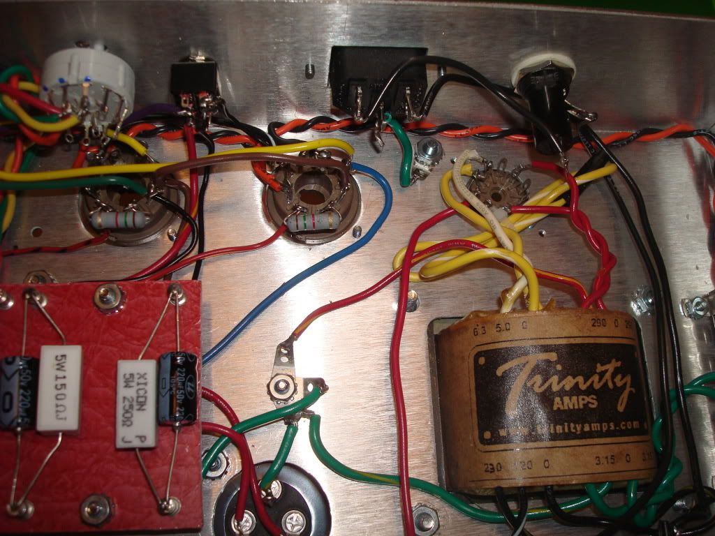
Day 7: August 18, 2011

Testing Day with Real Electricity ... AKA, I Was a Naughty Builder!

I actually sat down and attempted to go through the testing instructions that Trinity provided with the kit. Things began easy with the bit about plugging in and turning the power on with no tubes (not even a rectifier) plugged in. I measured the two pins getting power form the transformer - basically testing the transformer and not anything I actually did - and got proper readings. So far, so good.

From that point on, either my readings were screwy, I don't know how to take readings or both of my crappy Radio Shack meters are complete garbage! One meter is an old cheapier with a needle gage to read every possible thing on a few different scales. The other is an almost as cheap one with a digital readout - with the addition of black sharpie all over the display courtesy of my three year old. :shock:

As I progressed through the instructions (i.e. added the rectifier tube, standby on, then added the other tubes, etc.), I really began scratching my head. My digital meter gives all sorts of weird, crazy values that don't even seem to jive with my old needle meter. This was a quandary. It became instantly clear that I was never going to complete a full table of readings per the instructions using my brain and my two crappy meters. Choices:
1) Ask a billion questions as to what I'm doing wrong
2) Finally break down and buy a decent Fluke or equivalent meter
3) Double check everything again and not worry about 1 and 2.

I was naughty and chose #3. This is my second amp build. The first one fired up perfectly with no mistakes. Since I know I'm crazy anal about not making mistakes with component values or wire locations, and I know I did things right before, I figured I did it right this time. Therefore, I plugged in all the tubes, turned on the power, turned on the standby, and then looked for smoke, melting components or weird noises. When everything looked good, I dialled up the volumes on each channel to listen for noise or hum. Pretty quiet even when cranked (and not even in the shielded cab yet!). Finally a plugged in a guitar and slowly rolled the volume up.

Yikes! It works!

It definitely works, and sounds good, but I'm not sure if it works PROPERLY per design until I get a few questions answered.

1) Should the sIII's normal (Vol and Tone) channel be louder and brighter than it's 5 knob TMB channel? If so, mine is on the money.

2) Should the sIII normal channel's Tone control be not nearly as extreme as, for instance, the tone on a guitar? In other words, the tone control definitely rolls off treble, but never gets super dark and woofy - almost sounds like a well-voiced presence control. If so, mine works.

3) Should the EL84 mode on both channels be somewhat louder (at least at lower volume settings - haven't compared dimed settings yet) than the 6V6 mode? If so, again, mine seems right.

4) Should the boost be REALLY louder on than off? If so, mine is fine.


Plus, a few non tone/operation questions:

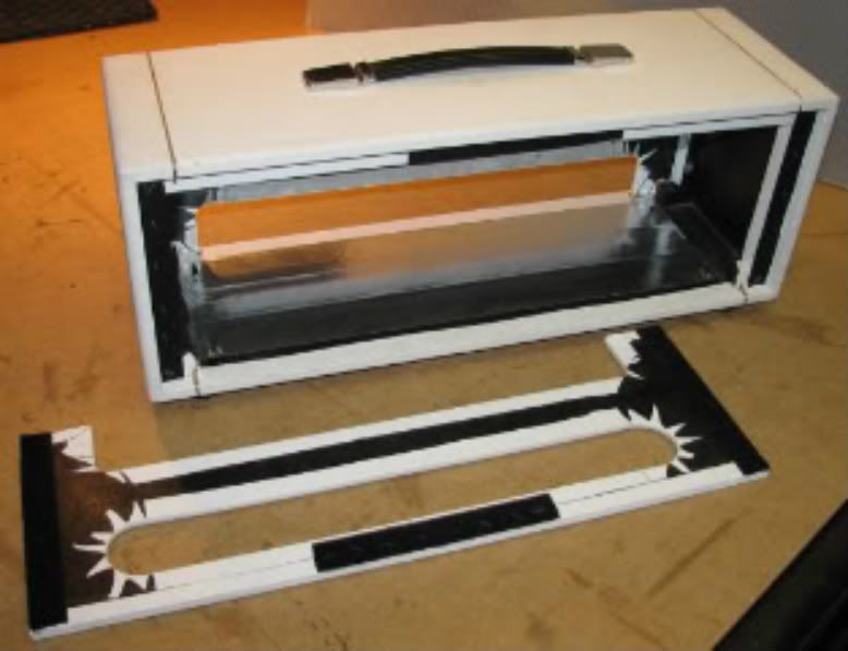
5) I notice the cabinet didn't come with any sheilding for the floor to fully encase the chassis. Is it worthwhile to glue on some aluminum foil there? Is it "standard" for most builders here?

6) I'm still going to solder the unused power transformer wires to the unused tags on the strip. 
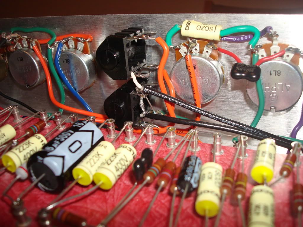
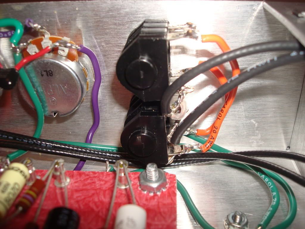
But what about the unused output transformer brown and blue wires? The instructions say to tue them off outside the chassis, but how? Right now, I have the ends taped and the wires coiled up. What else? Wire ties? Snip them? Don't snip them?

7) When I go in and put a few wire ties in before closing everything up (and checking those items per the suggestions above), I'm not sure what to do about the coax that goes from the gain to v2. Right now, it's sort of floating about the board given the length and natural stiffness of the cable. Is that good? I don't see a good place to wire tie it unless I choose some components on the board. Is that even a good thing? Is it better for that wire to be near the board or to be "floating" away from it?

_________________
Go Buckeyes!


Last edited by RMosack on Fri Oct 21, 2011 12:46 pm, edited 1 time in total.

Top
 Profile  
 
PostPosted: Sun Aug 21, 2011 3:35 pm 
Offline
Expert
Expert
User avatar

Joined: Sun May 20, 2007 1:45 pm
Posts: 1254
Location: YYZ
Congratulations (again)!! :D

OK to answer your questions:

1 - The sIII's TMB channel has it's gain throttled down compared to other types of 18W TMB. So yes, it's possible that the Normal channel may appear louder or gainier. You can easily tweak the TMB channel if you decide you want more kick out of it.

2 - That sounds about right. It will never get woofy, because it only acts on the treble frequencies.

3 - Kind of yes and no. Yes, a stock sIII v6 is like that - because 6V6s have a lot less gain and need more drive compared to EL84s. And no, because in my opinion it shouldn't be like that. I therefore recommend a modification to get the 6V6s working as hard as the EL84s.

4 - Absolutely. Boosted will be louder. When I play an sIII I leave the boost on all the time. :D

5 - It's a good idea to have foil on the base panel, to block outside interference from getting inside the amp.

6 - Put heatshrink over the unused wire ends so that there's some extra sleeving after the ends of the wires. Heat up the sleeving with a heat gun and then squish the extra bit with a pair of pliers, so that they seal. Next coil the wires and strap them neatly with tie wrap to the unused holes in the transformer core. This is the officiall Trinity-recommended way.

7 - I don't see a problem with it floating like that, as long as it can't move around.

_________________
Great tones come in small glass jars!


Top
 Profile  
 
PostPosted: Sun Aug 21, 2011 7:10 pm 
Offline
Experienced
Experienced
User avatar

Joined: Thu May 17, 2007 12:44 pm
Posts: 204
Location: Vancouver BC
What Zaphod said! Congrats! I use that aluminum foil tape for heater ducts for RF protection. It comes in a roll like duct tape so you can make about 200 amps with it! :thumbsup:

You can see how I put it in this 18 watt head cab I made (pic is kind of fuzzy)

http://i127.photobucket.com/albums/p146 ... 3673-1.jpg


Top
 Profile  
 
PostPosted: Sun Aug 21, 2011 9:15 pm 
Offline
Experienced
Experienced
User avatar

Joined: Wed Mar 31, 2010 5:47 pm
Posts: 341
Location: Oceanside, CA
Thanks for the replies.

Re #3: So far, I don't remotely mind the 6V6 being a little quieter. It's not a huge difference. Just a shade less overall volume. I kind of like it being a tad different. Besides, the 6V6 half is novelty. I built this thing because I had a hakering for a classic British EL84 amp. Maybe someday in the future I'll consider a change, but not now.


Re #4: Interesting note regarding leaving it on all the time. In a way, the amp seems more "Marshall-ey" with the boost on. With just a switch in the back and no footswitch or anything, I don't think of it as an on the fly selectable thing. Just sort of makes the TMB half into two slightly different flavored amps. So far, I've experimented with it on and off, with and without the normal channel jumpered in. Lots of fun flavors available, particularly given pick attack and guitar volume level.

It's even been more fun jumpering the amp with my Allen Old Flame for a little simultaneous Fender and Marshall flavor. In this case, the boost on seems to make the 18 watt side more "British". Pretty neat that with a little reverb on the Allen, you can't really tell exactly that one amp has reverb and one doesn't. Just a big, full sound.


Re #5: As far as the shielding for the floor of the head cab, I just used simple kitchen aluminum foil. To make it stick, I used some Krylong Easy-Tack Ropositionable Adhesive. It comes in a spray can that looks just like a paint can. My wife and kids have a hoard of artsy-craftsy supplies in the garage. In this case, it came in handy for an amp!

Actually, I've never owned a heat gun for shrink tubing. Once again, those art supplies. Turns out the wife's laminating tool blower thing works perfectly. Who knew?! :D

Re #6: Pending the answers to my post, I went ahead and did a simple fix. Not that hard to change it since it's outside the chassis anyway. I snipped the ends of the wire back so that the tinned bits weren't exposed. I then wrapped each wire end in electrical tape. That doesn't really seem enough, but it's a start. After that, I folded each wire back against itself about four times, with the taped bit captured in the middle (about a half fold). At that point, I wrapped the whole flat coil with tape at the point where the end was. One last fold, then a wire tie to hold it all in place. Did that for both wires. Seems pretty secure, but I'll look into the other method next time I have the thing open. At this point, it's all together and just too much fun to play!

Re #7: Yeah, with the chassis in the cab, the whole thing is upside down anyway. Instead of being elevated above the board, the cable is actually hanging a tad below the board. There's not that much play iin it anyway, so I don't think it actually touches the cabinet. Just happily suspended. I'll leave it as is for now.

_________________
Go Buckeyes!


Top
 Profile  
 
PostPosted: Mon Aug 22, 2011 12:24 am 
Offline
Expert
Expert
User avatar

Joined: Sun May 20, 2007 1:45 pm
Posts: 1254
Location: YYZ
RMosack wrote:
So far, I don't remotely mind the 6V6 being a little quieter. It's not a huge difference. Just a shade less overall volume.

It's probably only developing about 12W with the 6V6s, which translates to what sounds to the human ears as a shade less overall volume, as you reported. You will also be getting somewhat less breakup than with the EL84s.

_________________
Great tones come in small glass jars!


Top
 Profile  
 
PostPosted: Tue Aug 23, 2011 11:48 am 
Offline
Experienced
Experienced
User avatar

Joined: Wed Mar 31, 2010 5:47 pm
Posts: 341
Location: Oceanside, CA
zaphod wrote:
RMosack wrote:
So far, I don't remotely mind the 6V6 being a little quieter. It's not a huge difference. Just a shade less overall volume.

It's probably only developing about 12W with the 6V6s, which translates to what sounds to the human ears as a shade less overall volume, as you reported. You will also be getting somewhat less breakup than with the EL84s.


Interesting. 12 watts out of the 6V6 would be in line with the slight volume drop. Kind of neat, in a way, since the only other 6V6 amp I own is my almost 30 year old Fender Super Champ. That baby is rated at 18 watts out of a pair of 6V6 tubes. Much hotter amp. I suppose the way my sIII is currently wired up, the 12 watt output is in line with a Princeton Reverb, albeit entirely different circuitry.

For now, I kind of like the change of pace between the EL84 and 6V6. It's like I just built two totally different amps. But of course, it's inevitable that someday I'll be curious about what changes could be made to "heat up" the 6V6 side of things to bring it in line with th EL84 side. I'll definitely be posting and looking for those mods! :D

_________________
Go Buckeyes!


Top
 Profile  
 
PostPosted: Wed Dec 28, 2011 3:18 pm 
Offline
Experienced
Experienced
User avatar

Joined: Wed Mar 31, 2010 5:47 pm
Posts: 341
Location: Oceanside, CA
Thought I'd resurrect this thread since today should be new cabinet day.

Since I built the red beastie, I've been playing it through a 2x12 Avatar cab that I've had for a few years. It's loaded with a Celestion Gold and a Celestion Century Neo. I bought a Greenback months ago and it has been waiting around for a cab. The 1x12 Vintage style Lopo Line cab should be arriving today. Red tolex with white piping to match the Trinity head.

Can't wait to hear the combo of Trinity 18 and Greenback.

Just a few more hours...

_________________
Go Buckeyes!


Top
 Profile  
 
Display posts from previous:  Sort by  
Post new topic Reply to topic  [ 53 posts ]  Go to page 1, 2, 3  Next

All times are UTC - 5 hours [ DST ]


Who is online

Users browsing this forum: No registered users and 14 guests


You cannot post new topics in this forum
You cannot reply to topics in this forum
You cannot edit your posts in this forum
You cannot delete your posts in this forum
You cannot post attachments in this forum

Search for:
Jump to:  
cron
Powered by phpBB® Forum Software © phpBB Group