trinityamps.com

Trinity Amps Guitar Amp Forum
It is currently Tue Jul 16, 2024 11:36 am

All times are UTC - 5 hours [ DST ]


Post new topic Reply to topic  [ 20 posts ] 
Author Message
PostPosted: Tue Aug 21, 2007 2:53 pm 
Offline
Friend
Friend

Joined: Tue Aug 07, 2007 9:16 pm
Posts: 31
Location: Las Vegas, NV
Sorry guys, only amp porn here! I'm popping my amp building cherry with a Trinity sIII combo, and I've decided to post a pictorial of the process. Hopefully seeing one of these things go together step by step from a noob's perspective will encourage other first timers to take the dive into the amp building world. Or perhaps I'll send the whole thing up in flames at the end and send everyone running to Guitar Center for their next amp purchase. (Ooh, suddenly we have an element of suspense!)

Just a little background from the builder: I have approximately zero (as in none) electronics experience. My only experience with a soldering iron involves wiring a couple of strat pickguards. I do, however, enjoy building and tinkering with various things including guitars, old cars, and whatever else can capture my short attention span for more than a week at a time. I recently completed my first partscaster (strat copy) a few weeks ago, and decided I needed to build an amp to keep it company. "Start with a Champ clone," they told me, "to get your feet wet." "Wet feet are for wimps," I said, "I want 18 watts of hell and fury!"


Top
 Profile  
 
 Post subject:
PostPosted: Tue Aug 21, 2007 3:20 pm 
Offline
Friend
Friend

Joined: Tue Aug 07, 2007 9:16 pm
Posts: 31
Location: Las Vegas, NV
Day 1:

After opening the kit from Trinity and taking a careful inventory of all the parts, I read through the manual several times with the layout in hand. I must complement Stephen on the very thorough build manual. It gives a little background on the general principals of tube amps, and a healthy amount of tips and things to watch out for. It is not a step-by-step handholding type of deal, but anyone who is reasonably intelligent and has done a little homework through reading and the various DIY amp building sites should be able to work through it quite handily.

My first step was to organize all of the little electronic bits and pieces into a logical order for assembly. I found all of the capacitors to be clearly labelled and easy to identify, but being a noob, I'm not so quick to read resistor codes. So I broke out the multi meter, took resistance readings from all of them, and taped them to a labelled sheet of paper, to expedite the building of the turret board:
Image

Next was the connections on the backside of the board:

Image

And then I began with the top of the turret board. For this I printed out an extra copy of the sIII layout from the sticky at the top of this forum and used it as a scratch copy of sorts. I marked this sheet on each solder connection as it was completed, so that I was sure I didn't miss any. I also broke the board up into four logical sections during assembly so that I could stop periodically and recheck my work. I find it easier to check in small parts than to go back and check the whole board when I'm all done. To my mind, it seemed less overwhelming this way.

The first part of the board:

Image

The second part:

Image

You get the idea, so here's the completed board:

Image

Tomorrow I will start installing hardware into the chassis. Stay tuned!


Top
 Profile  
 
 Post subject:
PostPosted: Tue Aug 21, 2007 3:51 pm 
Offline
Holy Ghost
Holy Ghost
User avatar

Joined: Sun Mar 13, 2005 4:10 pm
Posts: 7519
Location: Canada
Very encouraging. Great pictorial!

_________________
Stephen
Web: www.trinityamps.com. Facebook: facebook.com/trinityamps. Twitter: @trinityamps


Top
 Profile  
 
 Post subject:
PostPosted: Tue Aug 21, 2007 10:07 pm 
Offline
Friend
Friend

Joined: Tue Aug 07, 2007 9:16 pm
Posts: 31
Location: Las Vegas, NV
Found a couple of hours to do a little work today, so let's see what we can get accomplished shall we?

So far I have completed the top of the turret board. I have elected not to solder on the flying leads just yet, as I would like to mock up the chassis with all the hardware in it, so I can see if there are any unusually long wires I need to account for. I don't want to get stuck wasting time with extending leads unnecessarily.

So let's start the chassis assembly shall we! First we start with the naked chassis:

Image

I started with the rear panel, installing the tube sockets, along with the tag strips for v1, the fuse holder, and the AC outlet:

Image

Then the heater wiring was run, starting at v1 and going towards the PT:

Image

After wiring in the tube heaters, I'm really starting to wish I had a head chassis. It really is quite tight in there!

Before I install the front panel hardware, I decided to wire the input jacks. I took a tip I found on one of the builder sites and installed them on the front of the chassis to wire them. This gave me lots of extra space to do the delicate wiring involved with these jacks. I did this before I installed the face plate, so as not to ruin the plexi panel:

Image

Well, that's as far as I got today. Next time I'll install the rest of the hardware, and mock up the chassis.


Top
 Profile  
 
 Post subject:
PostPosted: Wed Aug 22, 2007 6:42 am 
Offline
Holy Ghost
Holy Ghost
User avatar

Joined: Sun Mar 13, 2005 4:10 pm
Posts: 7519
Location: Canada
Looking good!

Make sure those Cliff Input. jacks are wired correctly. One has to be turned the opposite way to accommodate the chassis mounting screws.


Image

_________________
Stephen
Web: www.trinityamps.com. Facebook: facebook.com/trinityamps. Twitter: @trinityamps


Top
 Profile  
 
 Post subject:
PostPosted: Wed Aug 22, 2007 12:52 pm 
Offline
Friend
Friend

Joined: Tue Aug 07, 2007 9:16 pm
Posts: 31
Location: Las Vegas, NV
Wow, good catch! I actually had them wired as a mirror image of each other, and my TMB jacks were wired wrong. You should post that diagram in the sIII Docs! The diagram also shows an alternate grounding scheme, instead of all the grounds going to a common lug, which gets kind of crowded.

While we're talking grounding, is it okay to ground the input jacks to the bus bar, or should I go directly to the star ground as it shows in the layout? I would think it makes no difference, but then again, what do I know?


Top
 Profile  
 
 Post subject:
PostPosted: Wed Aug 22, 2007 1:31 pm 
Offline
Holy Ghost
Holy Ghost
User avatar

Joined: Sun Mar 13, 2005 4:10 pm
Posts: 7519
Location: Canada
Jimmy James wrote:
While we're talking grounding, is it okay to ground the input jacks to the bus bar, or should I go directly to the star ground as it shows in the layout?


I prefer to go from the input directly to the pre-amp star ground. You could connect the two input jack pairs together then go to the pre-amp star ground lug. I have done that.

But I'm sure your idea would work.

As for including, I agree. I try to send with each combo kit and post here. Glad we caught it!! It needs to be incorporated into the docs.

_________________
Stephen
Web: www.trinityamps.com. Facebook: facebook.com/trinityamps. Twitter: @trinityamps


Top
 Profile  
 
 Post subject:
PostPosted: Thu Aug 30, 2007 2:29 pm 
Offline
Friend
Friend

Joined: Tue Aug 07, 2007 9:16 pm
Posts: 31
Location: Las Vegas, NV
Well, the kids are back in school, so I've had some time to fire up the soldering iron. Per Stephen's diagram I have fixed the input jack wiring, and attached all of the "flying leads" to the board. Sadly I got distracted and there are no pix of this.

After installing the pots and mounting the board in the chassis, I began wiring with the "Bass" pot and working my way to the other end of the board:

Image

You'll notice I haven't finished wiring up the "Volume" pot for the TMB channel. I didn't have enough shielded cable leftover after the input jacks, so I'm waiting on some more to arrive.

Then I moved on to the Normal channel:

Image

And finally a shot of all of the control pots with the board. I tried my best to keep the leads neatly organized. I think I did a fair job for my first try, but I have learned a few tricks that will definitely help me do it better and faster next time. Oh yes, there will be a next time!

Image


Top
 Profile  
 
 Post subject:
PostPosted: Thu Aug 30, 2007 2:46 pm 
Offline
Friend
Friend

Joined: Tue Aug 07, 2007 9:16 pm
Posts: 31
Location: Las Vegas, NV
And now to connect the leads to the tube sockets. I started with the power tubes first, since they have fewer leads. I figured this would warm me up for the more detailed pre amp tube wiring:

Image

Note that these are only the leads from the board. I have not installed the trannies yet. I found it easier to wire the combo chassis with it standing on end, and this would get awkward with the extra weight of the iron installed. I will be tackling the High Voltage wiring in another stage of the build.

Next was the wiring for the preamp valves. This has proven the most difficult part of the build thus far. It's just a lot of detail work trying to route all of the wires to the pins, while keeping them crossing at 90 degree angles, etc. Doing it in a combo chassis doesn't make it any easier. Getting V1 wired up with the terminal strips and resistors was like doing open heart surgery on a hamster!!!

Image

I have been keeping an extra layout sheet handy to mark off all of the solder connections. I will also go back and triple check all of this later on:

Image

And here is a group shot of all of the tube wiring:

Image

I've got to say, it's a great feeling to go from the tangled mess of wires that I started with and seeing it all come together like this. But now it's late, and I need some sleep. Thankfully someone's been keeping my side of the bed warm for me!

Image


Top
 Profile  
 
 Post subject:
PostPosted: Thu Aug 30, 2007 2:55 pm 
Offline
Holy Ghost
Holy Ghost
User avatar

Joined: Sun Mar 13, 2005 4:10 pm
Posts: 7519
Location: Canada
Thjis is a great Great pictorial. I'll see if I can check it out for you. Maybe some others. Sorry you ran out of shielded cable. I would have sent some to you.

And, uh, what's the dog's name??

I fell off my chair when I saw that picture!! Fantastic!! :D

_________________
Stephen
Web: www.trinityamps.com. Facebook: facebook.com/trinityamps. Twitter: @trinityamps


Top
 Profile  
 
 Post subject:
PostPosted: Thu Aug 30, 2007 5:12 pm 
Offline
Friend
Friend

Joined: Tue Aug 07, 2007 9:16 pm
Posts: 31
Location: Las Vegas, NV
The bed warmer is named Molly. She's an Aussie Shepherd/Lab mix, and an awesome dog!

No worries about the shielded cable. I probably just overestimated what I would need for my input jacks and left myself short. I had a hell of a time finding it locally, but I needed to order a DPDT switch for my wah pedal online, so I just piggybacked the order. I started to ask you, but it takes so long to get stuff here from Canada!

Speaking of things coming from Canada, how's my cabinet coming along? It's the 1x12 with the custom cream tolex. I got my speaker today (Hellatone 30) and I got nowhere to stick it!


Top
 Profile  
 
 Post subject:
PostPosted: Thu Aug 30, 2007 6:53 pm 
Offline
Holy Ghost
Holy Ghost
User avatar

Joined: Sun Mar 13, 2005 4:10 pm
Posts: 7519
Location: Canada
Jimmy James wrote:
Speaking of things coming from Canada, how's my cabinet coming along? It's the 1x12 with the custom cream tolex. I got my speaker today (Hellatone 30) and I got nowhere to stick it!

Cab is built and is in the line-up to be tolexed.

_________________
Stephen
Web: www.trinityamps.com. Facebook: facebook.com/trinityamps. Twitter: @trinityamps


Top
 Profile  
 
 Post subject:
PostPosted: Sun Sep 02, 2007 6:12 pm 
Offline
Friend
Friend

Joined: Tue Aug 07, 2007 9:16 pm
Posts: 31
Location: Las Vegas, NV
Sweet! Could you send some pix before you ship? I'd love to put them in the build thread to wet some appetites!!!

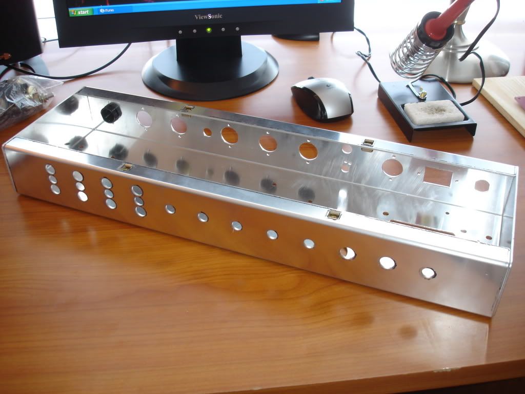
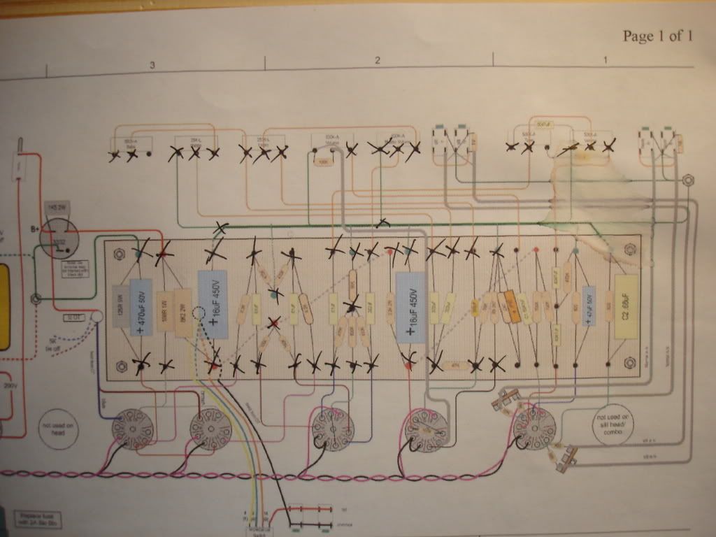
So I have started wiring the high voltage portion of the amp recently. My first step was to mount all of the related hardware: Power Transformer, Output Transformer (more on this later), cap can, switches, fuses, pilot light, and power outlet. Here's a pic of the Power tranny mounted in place:

Image

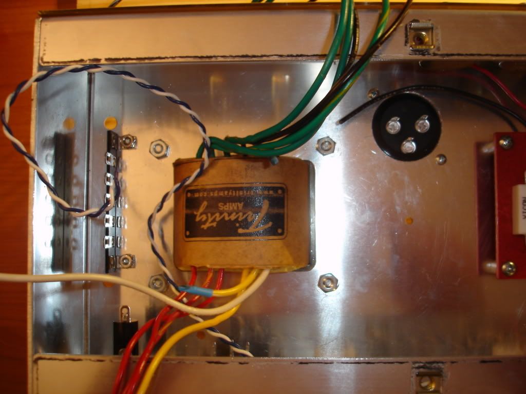
I mounted the OT at the same time, although you can't see it in the pic. I have to note here that I purposely waited to mount the trannies until after I had wired in the board. I figured that this way would be easier, since I could position the chassis for soldering without the bulk of the trannies. I neglected to notice that on the combo chassis, the access holed for the OT are located UNDER the turred board!! Thankfully I had plenty of slack in my leads, and was able to unmount the board and squeeze the OT wires through with little difficulty. Perhaps next time I will follow the advice in the build guide and mount everything first!

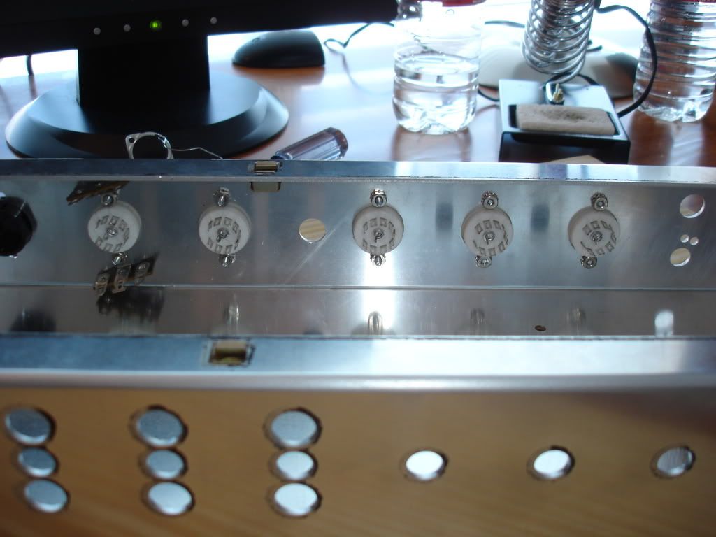
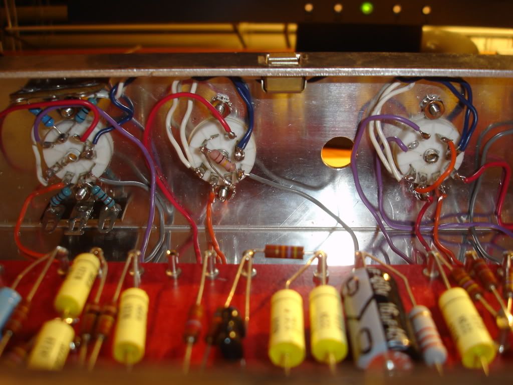
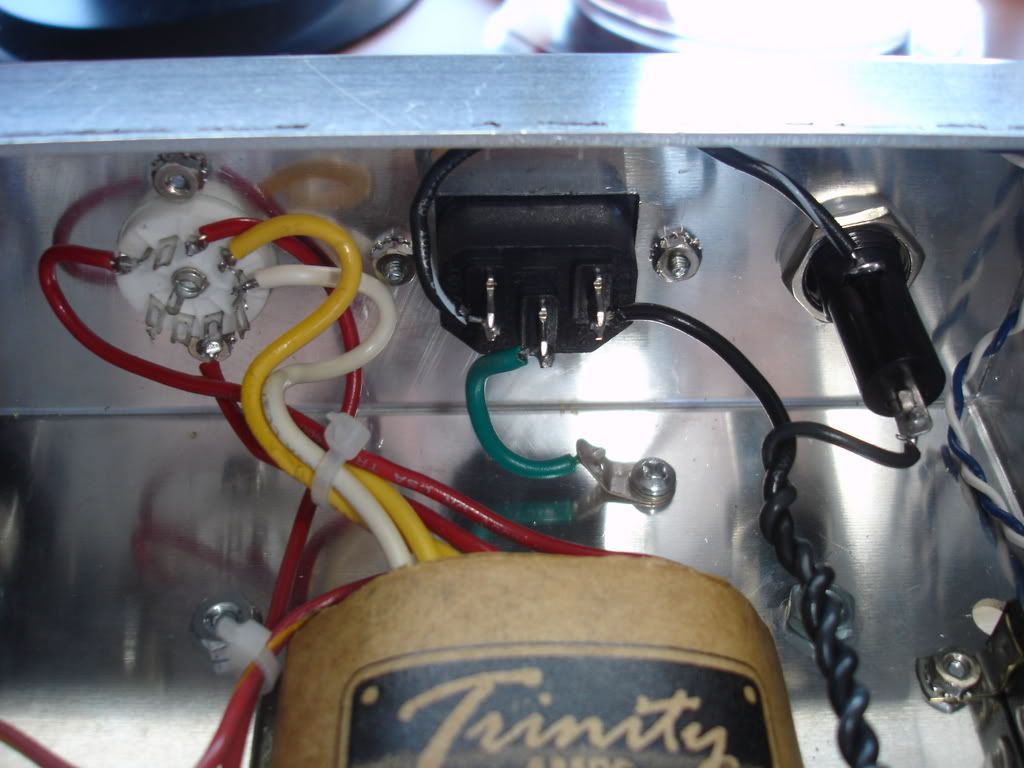
Next up was making the connections from the PT to the rectifier socket:

Image

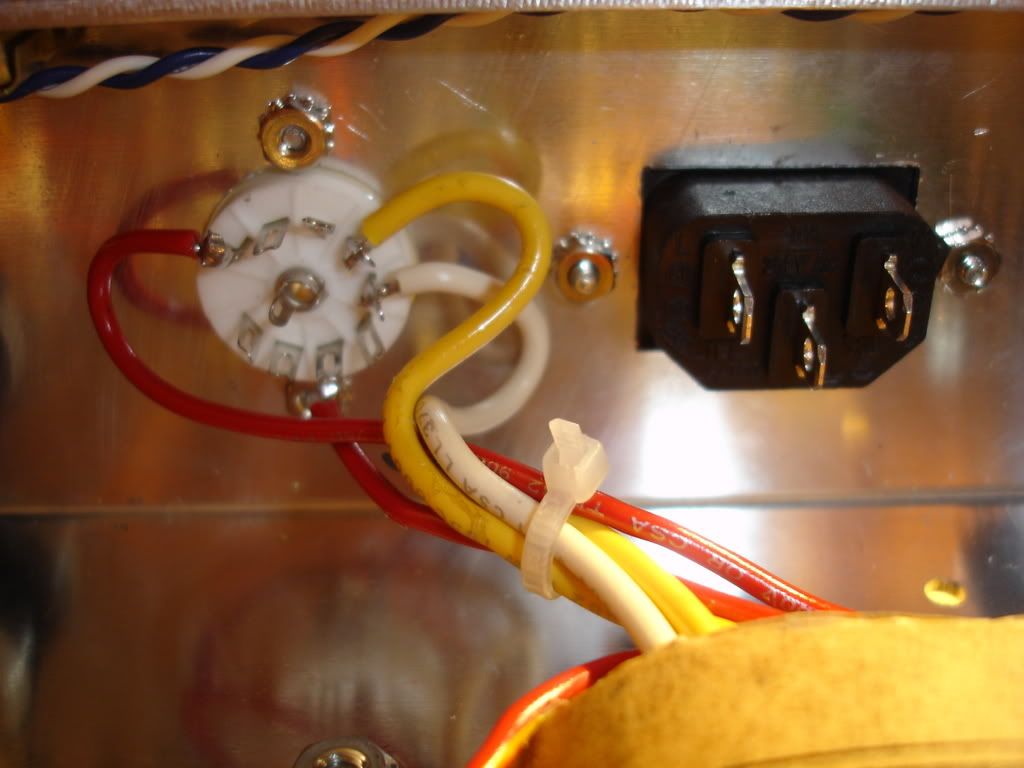
This does NOT complete the rectifer wiring, as I have yet to wire in the switches, or the mains supply yet.

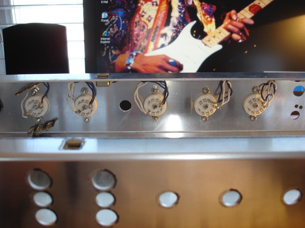
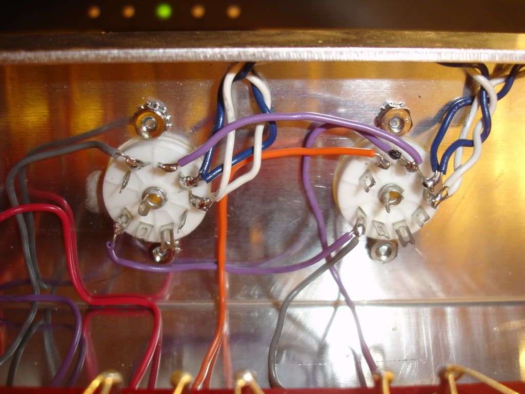
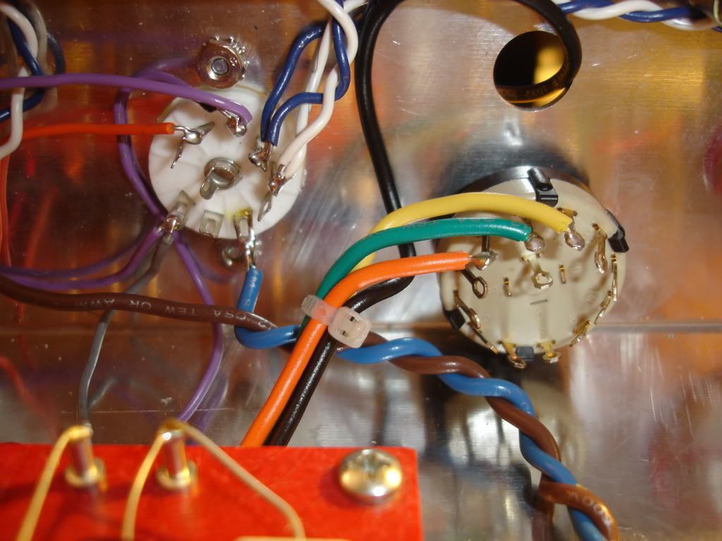
Here is a pic of the OT connections to the impedance switch and the power tubes. I have left the output jack out for the moment so you can see the switch more clearly:

Image

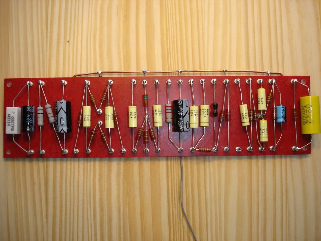
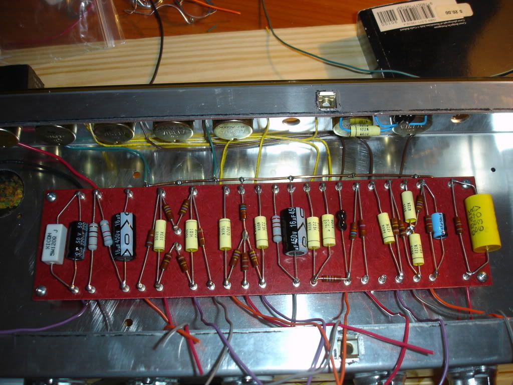
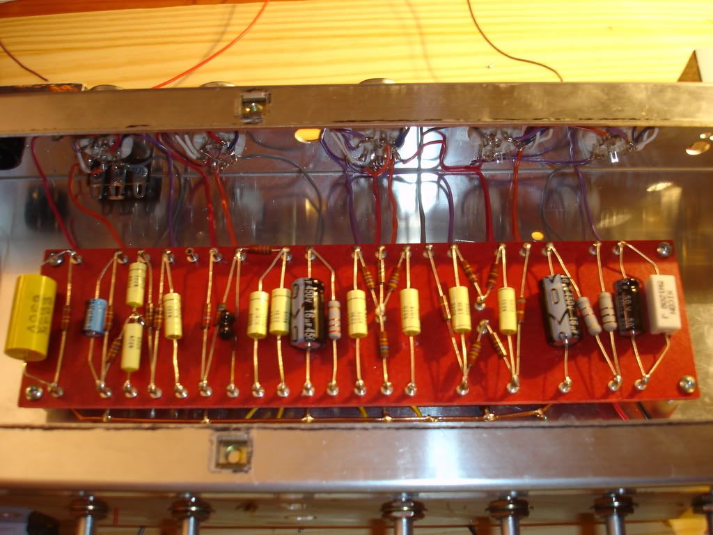
After that I made the connections from the board to the cap can, wired the heater fillaments to the terminal strip, and wired all of the transformer grounds. This is what we're left with:

Image

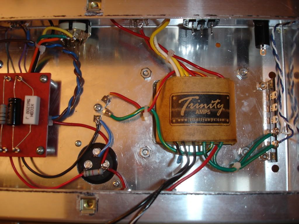
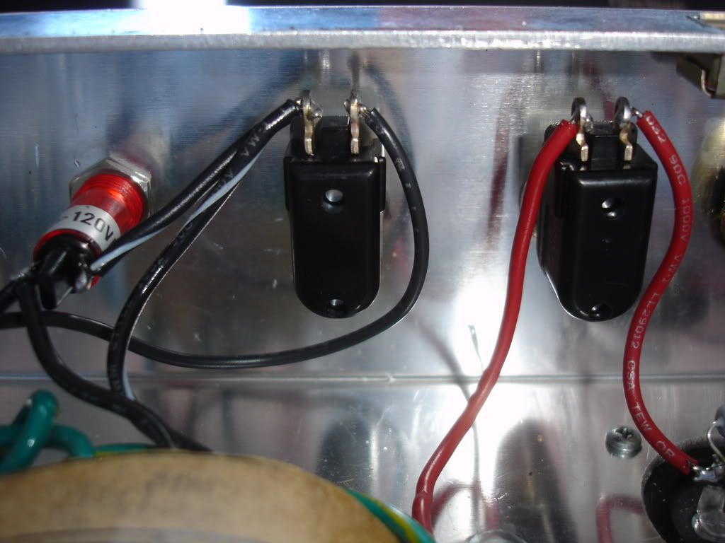
Next up is to wire up the switches, fuse, pilot light, and make the connections to the mains. I can almost smell the tubes burning!!!!


Top
 Profile  
 
 Post subject:
PostPosted: Mon Sep 03, 2007 8:20 am 
Offline
Holy Ghost
Holy Ghost
User avatar

Joined: Sun Mar 13, 2005 4:10 pm
Posts: 7519
Location: Canada
Your pictorial is great. The quality of your build looks very good too. Keep up the good work.

_________________
Stephen
Web: www.trinityamps.com. Facebook: facebook.com/trinityamps. Twitter: @trinityamps


Top
 Profile  
 
 Post subject:
PostPosted: Sun Sep 09, 2007 10:01 pm 
Offline
Experienced
Experienced
User avatar

Joined: Mon Mar 14, 2005 9:02 pm
Posts: 308
Location: Brampton
I bet you were dog tired after putting all that together.

_________________
Guitologist at Large
"How does that feel?"


Top
 Profile  
 
 Post subject:
PostPosted: Thu Sep 13, 2007 5:33 am 
Offline
Friend
Friend

Joined: Tue Aug 07, 2007 9:16 pm
Posts: 31
Location: Las Vegas, NV
Finished wiring up the chassis today! Decided to rewire my input jacks to clean things up a bit. Since it was one of the first things I did on the project, the work was a bit sloppy. Now that I've had lots of soldering practice, I thought I might do a better job! Also finished wiring the high voltage bits.

Here's a pic of the mains:

Image

And the switches:

Image

And here's the rest of the guts. I also decided to re wire the heater filaments from the tranny, this time braiding the leads. Just being extra anal I guess, but I've noticed that almost everyone does it this way, so...

Image

Now to double, and triple check everything! Hope to fire it up this weekend.


Top
 Profile  
 
 Post subject:
PostPosted: Thu Sep 13, 2007 6:31 am 
Offline
Holy Ghost
Holy Ghost
User avatar

Joined: Sun Mar 13, 2005 4:10 pm
Posts: 7519
Location: Canada
Quote:
Now to double, and triple check everything! Hope to fire it up this weekend.


I like to use my meter on Continuity Check and check each connection with an audible beep. Nice if you got one. Then I mark up the drawing.

One thing, check all your ground points!!

Good luck. Keep us posted.

_________________
Stephen
Web: www.trinityamps.com. Facebook: facebook.com/trinityamps. Twitter: @trinityamps


Top
 Profile  
 
 Post subject:
PostPosted: Tue Sep 18, 2007 1:33 pm 
Offline
Friend
Friend

Joined: Tue Aug 07, 2007 9:16 pm
Posts: 31
Location: Las Vegas, NV
Quote:
One thing, check all your ground points!!


That turned out to be quite a bit of foreshadowing! After running through the checklist and firing it up, I found that the tone and volume controls for the normal channel were not working. It was running wide open!! (And sounding mighty fine 8) ). Turns out I had neglected to ground the normal channel's controls. Luckily that was an easy fix, and I was soon on my way. Sadly it was late by the time I got it sorted out, so I haven't yet had a chance to really crank it.

Here are my voltages:

V1 12ax7
Pin Volts
1 137
3 .94
6 136
8 .96

V2 12ax7
Pin Volts
1 163
3 1.5
6 253
8 163

V3 12ax7 PI
Pin Volts
1 203
2 49
3 70
6 199
7 49
8 70

V4 el84
Pin Volts
3 10.3
7 330
9 319

V5 el84
Pin Volts
3 10.3
7 329
9 319

V6 ez81
Pin Volts
1 299
3 344
7 299

The voltages seem kind of low across the board, but they all seem to be within 10% of spec.

Can't wait to get home tonight and put it through its paces!! Stephen also sent some good news today, my cab is almost done!!!


Top
 Profile  
 
 Post subject:
PostPosted: Tue Sep 18, 2007 1:37 pm 
Offline
Holy Ghost
Holy Ghost
User avatar

Joined: Sun Mar 13, 2005 4:10 pm
Posts: 7519
Location: Canada
Quote:
Turns out I had neglected to ground the normal channel's controls


Hah!! :lol: It happens to the best of us!!! Crank it Up!

_________________
Stephen
Web: www.trinityamps.com. Facebook: facebook.com/trinityamps. Twitter: @trinityamps


Top
 Profile  
 
 Post subject:
PostPosted: Sun Sep 23, 2007 12:33 pm 
Offline
User avatar

Joined: Thu Feb 09, 2006 2:04 pm
Posts: 9
Check your mains AC voltage. If it's a little low then it will result in lower voltages throughout.

Anyway Congrats!! Good job!!


Top
 Profile  
 
Display posts from previous:  Sort by  
Post new topic Reply to topic  [ 20 posts ] 

All times are UTC - 5 hours [ DST ]


Who is online

Users browsing this forum: No registered users and 32 guests


You cannot post new topics in this forum
You cannot reply to topics in this forum
You cannot edit your posts in this forum
You cannot delete your posts in this forum
You cannot post attachments in this forum

Search for:
Jump to:  
Powered by phpBB® Forum Software © phpBB Group