trinityamps.com

Trinity Amps Guitar Amp Forum
It is currently Tue Apr 23, 2024 10:30 am

All times are UTC - 5 hours [ DST ]


Post new topic Reply to topic  [ 22 posts ]  Go to page 1, 2  Next
Author Message
 Post subject: Dual Rectifier
PostPosted: Thu Jan 13, 2011 6:48 pm 
Offline
Experienced
Experienced

Joined: Fri Aug 27, 2010 8:57 pm
Posts: 226
Location: Dallas, Tx
Hello,

I have been lurking here for about 6 months now reading and learning and am getting ready to order the Plexi head kit.

I play a variety of styles from classic blues to modern progressive rock. I like the squishy, spongy feel of a tube rectifier but I also want the tight, punchy feel of a diode rectifier so I am looking to build a dual rectifier 18 watt Plexi.

Here is what I had in mind:
Attachment:
DualRect1.jpg
DualRect1.jpg [ 38.85 KiB | Viewed 16775 times ]


I want to use a tranny with 2 HV secondary taps such as the Heyboer HTS-9144 (280-250-0-250-280) or HTS-5199 (300-260-0-260-300) as I do not want to use a 'sag resister' on the SS rectifier.

Which one of those trannies would be best? or is there another better one to use?

Which one would require the least amount of modifying of the rest of the circuit? (plate, screen resisters etc.)

Stephen, would I be able to order one of these through you or would I have to order it myself?

Thanks,

Les

_________________
Les

http://www.soundclick.com/unimind


Top
 Profile  
 
 Post subject: Re: Dual Rectifier
PostPosted: Fri Jan 14, 2011 10:15 pm 
Offline
Holy Ghost
Holy Ghost
User avatar

Joined: Sun Mar 13, 2005 4:10 pm
Posts: 7519
Location: Canada
Interesting idea but haventtried it. Dont have those trannies either. If you replace the rect wit a SS, you know it will be higher B+, so you could drop a zener in at the same time.

_________________
Stephen
Web: www.trinityamps.com. Facebook: facebook.com/trinityamps. Twitter: @trinityamps


Top
 Profile  
 
 Post subject: Re: Dual Rectifier
PostPosted: Fri Jan 14, 2011 10:49 pm 
Offline
Experienced
Experienced

Joined: Fri Aug 27, 2010 8:57 pm
Posts: 226
Location: Dallas, Tx
Right, that's why I wanted the tranny with the lower voltage tap.

Would using the zener(s) result in any sag? I really want to avoid sag on the ss rect.

Also, what value zener would I need to bring the voltage down to equivalent with the EZ81? Seems I would need to drop it by around 30+ volts?

_________________
Les

http://www.soundclick.com/unimind


Top
 Profile  
 
 Post subject: Re: Dual Rectifier
PostPosted: Fri Jan 14, 2011 11:19 pm 
Offline
Expert
Expert
User avatar

Joined: Sun Feb 17, 2008 4:47 pm
Posts: 960
Location: Toronto, Canada.
No sag with the added Zener.

Not sure if what Zener you need exactly. If the SS recto only puts out 30V like you say on the 18W amp then you would just need a 30V Zener diode from the HT CT to ground.


If it was me I'd just switch rectos and not worry about the increase or decrease in voltage. The difference in recto type and difference in switch make the two even more noticeable and versatile imo. I have done this in an amp of my own with good results.

_________________
http://pdfelectronics.com


Top
 Profile  
 
 Post subject: Re: Dual Rectifier
PostPosted: Sun Jan 16, 2011 6:52 pm 
Offline
Experienced
Experienced

Joined: Fri Aug 27, 2010 8:57 pm
Posts: 226
Location: Dallas, Tx
Thanks for the replies.

I am planning on adding the VRM to the amp so I can just use that to bring down the voltage a little when using the SS recto.

_________________
Les

http://www.soundclick.com/unimind


Top
 Profile  
 
 Post subject: Re: Dual Rectifier
PostPosted: Wed Mar 16, 2011 1:33 am 
Offline
Experienced
Experienced

Joined: Fri Aug 27, 2010 8:57 pm
Posts: 226
Location: Dallas, Tx
From bpkuder's thread:
zaphod wrote:
Be aware that the amp will sound less brown with SS rectifiers.

In keeping with my heavily modded amp, 8) I was looking for more options. I had planned from the beginning to have dual rectifiers for the different sounds they each give.
zaphod wrote:
Also, the B+ voltage will go too high unless you also stick some zeners after the SS rectifiers to knock some volts off.
My idea was to use a voltage regulator (like the VVR/VRM) to control the B+.

Here is what I did:
Attachment:
dualrect.jpg
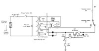
dualrect.jpg [ 46.47 KiB | Viewed 16521 times ]

My plan was to use the VRM to bring down the voltage to match the B+ of the EZ81. It was working at first. I was able to dial the voltage to where it matched the ez81 but then one day I noticed the voltage going way low (I had the VM clipped to the B+ so I could monitor it while playing) and my guitar sounded funny (buzzy/farty) and my son said "that doesn't sound good". I turned it off and ever since then the VRM does not seem to work right. In cathode bias the VRM 1 meg pot only varies the voltage from 339 all the way down to 341 all the way up. I should be able to vary it from 35-40 volts up to 350-370 volts (which I was able to do at first) so something is going on in the VRM.

And just so you know, I am not using the VRM like you would for power scaling an amp. I am strictly using it to dial back the B+ of the SS rectifier. Like a trim pot (actually I bought a 1meg trim pot for the VRM but it was only rated up to 300 volts so I didn't use it) once I have the voltage set I leave it there.

So the question is, what could be wrong with the VRM? Could it be the MOSFET? And how do I begin to test it?

_________________
Les

http://www.soundclick.com/unimind


Top
 Profile  
 
 Post subject: Re: Dual Rectifier
PostPosted: Wed Mar 16, 2011 12:19 pm 
Offline
Expert
Expert
User avatar

Joined: Sun May 20, 2007 1:45 pm
Posts: 1254
Location: YYZ
Shouldn't the VRM come after the first filter cap? The VRM itself should be fairly easy to test. Do you get a varying voltage at the output, as you vary the pot? Is the voltage at the MOSFET's gate varying as you turn the pot?

kurtlives wrote:
If the SS recto only puts out 30V like you say on the 18W amp then you would just need a 30V Zener diode from the HT CT to ground.

The recommended way is to place the zener(s) in the B+ line immediately after the first filter cap, same way as you would use a VRM. This results in less stress to the zener(s) and also a drop that's closer to the spec zener voltage. Also for safety I tend to chain together a few zeners of lower voltage. So for 30V we could put five 6V 5W zeners on a piece of tag strip, and that will split the power dissipation up evenly between the zeners, and if any one zener blows you're only out by 6V and not 30V. FYI zeners go short circuit when they blow.

kurtlives wrote:
If it was me I'd just switch rectos and not worry about the increase or decrease in voltage. The difference in recto type and difference in switch make the two even more noticeable and versatile imo. I have done this in an amp of my own with good results.

If you don't zener down the voltage, then you must also change the power amp cathode resistor not to burn out the EL84s. The bias points of the preamp tubes will also change, and the preamp will sound a lot cleaner, which may or may not be desired.

_________________
Great tones come in small glass jars!


Top
 Profile  
 
 Post subject: Re: Dual Rectifier
PostPosted: Wed Mar 16, 2011 12:23 pm 
Offline
Friend
Friend

Joined: Thu Mar 10, 2011 10:12 am
Posts: 23
Location: Woodbridge, VA
This is a really interesting post for me.

I recently completely rebuilt my 5F6A Bassman variation built in '98. One of the things I did was exactly like the first rendition to add a SS rectifier. It works but the B+ jumps almost 40V and the bias is way too cold, which overheats the amp. I haven't had time to fool with it yet but I was just going to calculate a dropping resistor and add that. However the Zener looks like a cool option.

Any opinions on just a dropping resistor?

Thanks


Top
 Profile  
 
 Post subject: Re: Dual Rectifier
PostPosted: Wed Mar 16, 2011 1:35 pm 
Offline
Experienced
Experienced

Joined: Fri Aug 27, 2010 8:57 pm
Posts: 226
Location: Dallas, Tx
zaphod wrote:
Shouldn't the VRM come after the first filter cap?
I've heard that but I also thought I saw it placed between the standby and the first filter cap with success. After the first cap it would then also apply to the tube rectifier as well when I switch to the tube. I would need to switch the VRM in only for the SS rectifier which makes wiring that much more complicated. Maybe I could do it with a 4 pole double throw switch but I don't know that I can get one rated for 400+ volts. One of the things I tried was to put a 400 volt 32uf cap right after the diodes (to ground) before the VRM but it was taking 1-2 minutes to charge up and would sag big time so I took it out. Maybe it wasn't big enough or I needed a resistor there as well. This is one of my limited knowledge areas.

zaphod wrote:
Do you get a varying voltage at the output, as you vary the pot? Is the voltage at the MOSFET's gate varying as you turn the pot?
Right now the voltage coming out of the VRM only varies by a few volts. I will test the gate tonight.

zaphod wrote:
The recommended way is to place the zener(s) in the B+ line immediately after the first filter cap, same way as you would use a VRM. This results in less stress to the zener(s) and also a drop that's closer to the spec zener voltage. Also for safety I tend to chain together a few zeners of lower voltage. So for 30V we could put five 6V 5W zeners on a piece of tag strip, and that will split the power dissipation up evenly between the zeners, and if any one zener blows you're only out by 6V and not 30V. FYI zeners go short circuit when they blow.
Again this makes for complicated switching to switch between tube and SS rectifiers. If I could put them right after the rectifier diodes then maybe this could work.

_________________
Les

http://www.soundclick.com/unimind


Last edited by Unimind on Wed Mar 16, 2011 1:43 pm, edited 2 times in total.

Top
 Profile  
 
 Post subject: Re: Dual Rectifier
PostPosted: Wed Mar 16, 2011 1:39 pm 
Offline
Experienced
Experienced

Joined: Fri Aug 27, 2010 8:57 pm
Posts: 226
Location: Dallas, Tx
Casey4s wrote:
Any opinions on just a dropping resistor?
I did not want to use a dropping resistor because I did not want any sag. For me the whole point of the SS rectifier was to stiffen up the feel of the amp. Having the resistor would simulate the sag of the tube recto and defeat the purpose.

_________________
Les

http://www.soundclick.com/unimind


Top
 Profile  
 
 Post subject: Re: Dual Rectifier
PostPosted: Wed Mar 16, 2011 2:00 pm 
Offline
Friend
Friend

Joined: Fri Oct 15, 2010 10:41 am
Posts: 48
Are you sure you were set to cathode bias when you had trouble with the VVR? You need a dual gang pot to use a VVR on fixed bias, like the Dana Hall VVR2 or 3.

Is your standby switch close to the VVR? You could put a DPST Standby to add another standby before the VVR then stick a big filter cap and bleeder resistor (or 2 in series) to ground between the diodes and the new standby.


Top
 Profile  
 
 Post subject: Re: Dual Rectifier
PostPosted: Wed Mar 16, 2011 2:07 pm 
Offline
Experienced
Experienced

Joined: Fri Aug 27, 2010 8:57 pm
Posts: 226
Location: Dallas, Tx
ForcedFire wrote:
Are you sure you were set to cathode bias when you had trouble with the VVR? You need a dual gang pot to use a VVR on fixed bias, like the Dana Hall VVR2 or 3.
Well yes I was. But again I am not using the VRM to scale the amp. Just using it to lower the B+ coming off the SS recto before the standby switch. And I should add that this is not a Hall VRM. It's a DIY VVR based on Stephen's VVR.

ForcedFire wrote:
... then stick a big filter cap and bleeder resistor (or 2 in series) to ground between the diodes and the ... standby.
I think that is what I was/am missing. Any thoughts on exact size/values of caps and resistors to use there?

_________________
Les

http://www.soundclick.com/unimind


Top
 Profile  
 
 Post subject: Re: Dual Rectifier
PostPosted: Wed Mar 16, 2011 2:47 pm 
Offline
Experienced
Experienced

Joined: Fri Aug 27, 2010 8:57 pm
Posts: 226
Location: Dallas, Tx
So here is a schem with the VR after the first filter cap.
Attachment:
dualrect2.jpg
dualrect2.jpg [ 50.18 KiB | Viewed 16485 times ]

It seems to me that the OT primary will now see higher voltage (+20 to +30) when using the SS retco. That would mean higher voltage on the el84 plates. In my amp running cathode bias I would see about 360 volts on the plates and in fixed bias I would see around 380 so my biasing would be way off when I switch to the SS recto. So I think I really need to solve this before the first filter cap.

_________________
Les

http://www.soundclick.com/unimind


Top
 Profile  
 
 Post subject: Re: Dual Rectifier
PostPosted: Wed Mar 16, 2011 3:12 pm 
Offline
Expert
Expert
User avatar

Joined: Sun May 20, 2007 1:45 pm
Posts: 1254
Location: YYZ
Unimind wrote:
ForcedFire wrote:
Are you sure you were set to cathode bias when you had trouble with the VVR? You need a dual gang pot to use a VVR on fixed bias, like the Dana Hall VVR2 or 3.
Well yes I was. But again I am not using the VRM to scale the amp. Just using it to lower the B+ coming off the SS recto before the standby switch. And I should add that this is not a Hall VRM. It's a DIY VVR based on Stephen's VVR.

That's correct, You can use the basic VVR on its own, if you're only using it for a set voltage drop, and you don't redajust the voltage drop after biasing your power tubes.

BTW its by far easier to get rid of your EZ81 rectifier and replace it with UF4007 diodes followed by a 120 ohm 10W sag resistor, which will simulate the sag of an EZ81. If you place the sag resistor after the first filter cap, you can then have a switch which either selects the sag resistor or zener(s). That will allow to easily chose between the stiffer feel of SS rectification or the softer compressed feel of a tube rectifier, and without infringing any of Randall Smith's patents! :lol: Just remember never to switch between them while the amp is switched on.

_________________
Great tones come in small glass jars!


Top
 Profile  
 
 Post subject: Re: Dual Rectifier
PostPosted: Wed Mar 16, 2011 3:48 pm 
Offline
Experienced
Experienced

Joined: Fri Aug 27, 2010 8:57 pm
Posts: 226
Location: Dallas, Tx
zaphod wrote:
BTW its by far easier to get rid of your EZ81 rectifier and replace it with UF4007 diodes followed by a 120 ohm 10W sag resistor, which will simulate the sag of an EZ81. If you place the sag resistor after the first filter cap, you can then have a switch which either selects the sag resistor or zener(s). That will allow to easily chose between the stiffer feel of SS rectification or the softer compressed feel of a tube rectifier, and without infringing any of Randall Smith's patents! :lol: Just remember never to switch between them while the amp is switched on.

But then I would be running the SS recto all the time (which may be fine) but with the switch after the first filter cap I would still have the issue of 375+ volts on the OT and plates. Maybe I should go read some of those patents to get some ideas. 8) :wink:

_________________
Les

http://www.soundclick.com/unimind


Top
 Profile  
 
 Post subject: Re: Dual Rectifier
PostPosted: Wed Mar 16, 2011 4:13 pm 
Offline
Expert
Expert
User avatar

Joined: Sun May 20, 2007 1:45 pm
Posts: 1254
Location: YYZ
No, you would be running the correct B+ voltage. It would either be coming to the amp through a 120 ohm resistor for sag or through zener(s) for no sag, depending on the switch position. But the voltage would be about the same at idle. An EZ81 has an effective internal resistance of around 110 ohms, so a 120 ohm resistor does a great job of emulating an EZ81.

_________________
Great tones come in small glass jars!


Top
 Profile  
 
 Post subject: Re: Dual Rectifier
PostPosted: Wed Mar 16, 2011 4:51 pm 
Offline
Experienced
Experienced

Joined: Fri Aug 27, 2010 8:57 pm
Posts: 226
Location: Dallas, Tx
zaphod wrote:
No, you would be running the correct B+ voltage.
The OT primary (and on to plates) is taken off the B+ before the first filter cap. This should see the full output of the rectifier, correct? Which will be higher for SS diodes than the EZ81 around 360-380 volts. Then the dropping or sag resistor switch will be after the first filter cap which will bring the B+ down for the screens and on to the rest of the amp. Is it a problem to have the higher voltage on the OT primary and output plates? Or do you just need to compensate by adjusting the cathode bias resistor (and in my case the fixed bias voltage)?
Edit: Or does the dropping/sag resistors affect the voltage before the first filter as well somehow? :?
Attachment:
dualrect3.jpg
dualrect3.jpg [ 51.42 KiB | Viewed 16473 times ]

_________________
Les

http://www.soundclick.com/unimind


Top
 Profile  
 
 Post subject: Re: Dual Rectifier
PostPosted: Wed Mar 16, 2011 5:47 pm 
Offline
Expert
Expert
User avatar

Joined: Sun May 20, 2007 1:45 pm
Posts: 1254
Location: YYZ
Unimind wrote:
The OT primary (and on to plates) is taken off the B+ before the first filter cap. This should see the full output of the rectifier, correct? Which will be higher for SS diodes than the EZ81 around 360-380 volts.

That's incorrect. Normally the OT is connected *at* the first filter cap, possibly via a Standby switch. In this case we insert a sag resistor or zener(s) between the filter cap and the OT. One cool trick could be to use an ON-OFF-ON switch for the Standby switch. One of the ON positions would give the sag resistor, and the other ON position would select the zener for stiffness.

_________________
Great tones come in small glass jars!


Top
 Profile  
 
 Post subject: Re: Dual Rectifier
PostPosted: Wed Mar 16, 2011 8:26 pm 
Offline
Experienced
Experienced

Joined: Fri Aug 27, 2010 8:57 pm
Posts: 226
Location: Dallas, Tx
Well the VVR seems to be working now for the most part. I must have a bad solder joint somewhere in it. But I noticed in checking voltages that the output tubes have different voltages on pin 7. With the EZ81 in cathode bias B+ is 338, V4 has 317 and V5 has 327. In fixed bias B+ is 364, V4 has 318 and V5 has 355. V4 seems way off to me. What would cause this and is it a major problem?

Edit: OK so the problem was I had the master volume all the way up and so it seems the bright channel was drawing load on the one side. When I turned the master down I read 357 volts on both V4 and V5 with a B+ of 364.

_________________
Les

http://www.soundclick.com/unimind


Top
 Profile  
 
 Post subject: Re: Dual Rectifier
PostPosted: Thu Mar 17, 2011 12:07 am 
Offline
Experienced
Experienced

Joined: Fri Aug 27, 2010 8:57 pm
Posts: 226
Location: Dallas, Tx
Here are my current voltages. Things look pretty consistent.

Rectifier: EZ81
Bias: Cathode
B+: 338.3
V4
Pin 3: 11.32 Pin 7: 326 Pin 9: 317.6
V5
Pin 3: 11.28 Pin 7: 327.4 Pin 9: 317.3

Bias: Fixed
B+: 356.6
V4
Pin 3: .025 Pin 7: 348.6 Pin 9: 339.5
V5
Pin 3: .025 Pin 7: 349.8 Pin 9: 339.5

Rectifier: Diodes
Bias: Cathode
B+: 345
V4
Pin 3: 11.50 Pin 7: 332.8 Pin 9: 324.7
V5
Pin 3: 11.52 Pin 7: 335.4 Pin 9: 325.4

Bias: Fixed
B+: 354.5
V4
Pin 3: .025 Pin 7: 347 Pin 9: 338.1
V5
Pin 3: .025 Pin 7: 348.6 Pin 9: 338.5

_________________
Les

http://www.soundclick.com/unimind


Top
 Profile  
 
Display posts from previous:  Sort by  
Post new topic Reply to topic  [ 22 posts ]  Go to page 1, 2  Next

All times are UTC - 5 hours [ DST ]


Who is online

Users browsing this forum: No registered users and 12 guests


You cannot post new topics in this forum
You cannot reply to topics in this forum
You cannot edit your posts in this forum
You cannot delete your posts in this forum
You cannot post attachments in this forum

Search for:
Jump to:  
cron
Powered by phpBB® Forum Software © phpBB Group