trinityamps.com

Trinity Amps Guitar Amp Forum
It is currently Sun Jun 30, 2024 12:33 pm

All times are UTC - 5 hours [ DST ]


Post new topic Reply to topic  [ 4 posts ] 
Author Message
PostPosted: Mon Feb 18, 2013 3:17 pm 
Offline

Joined: Sun Feb 17, 2013 9:07 pm
Posts: 3
Hello All,
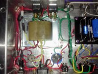
First 18 Watt TMB build and I have some questions about some voltages that don't seem in line. Let me say that the amp seems to be operating fine and sounds fantastic.

It is basically the Ceri@tone layout without the Diode setup on the Rectifier tube. Mojo trannies.
Tubes are Electro Harmonix 6CA4, Ruby EL84CZ, Ruby 12AX7AC7 HG, Ruby 7025SS HG, and an EH12AX7 PI.

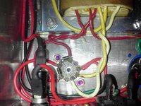
I installed a Tube/SS rectifier setup with a switch. IN4007 off of pins 1 and 7 V6 to Pin 6 to one side of switch, and a wire from pin 3 to switch. Voltages are-

V6- Pin 1-7= 301v
Pin 3= 370v, 392v SS

V4 and V5- Pin 3=8.2v, 9.2 SS
Pin 7= 247v, 262v SS
Pin 9= 257v, 272v SS

Curious as to why V6 pin 3 seems high, and V4-V5 voltages seem low. I didn't check V1-V3 since I did the rec mod. Thoughts?

Thanks in advance!

Mike


Attachments:
0218131214.jpg
0218131214.jpg [ 442.42 KiB | Viewed 4609 times ]
0218131214a.jpg
0218131214a.jpg [ 558.26 KiB | Viewed 4609 times ]
0218131215a.jpg
0218131215a.jpg [ 465.54 KiB | Viewed 4609 times ]
Top
 Profile  
 
PostPosted: Mon Feb 18, 2013 7:45 pm 
Offline
Experienced
Experienced
User avatar

Joined: Wed Aug 26, 2009 11:27 pm
Posts: 273
Location: Ontario
I pretty sure pin 6 as with all other unused pins of an ez81 / 6ca4 are internal connections. So you probably don't want to use pin 6 as a tag point. But what you want to do is us a tag board for this instead. And looking at the Ceri@tone layout the diodes don't seem to be hooked to a rectifer switch. but along with the cap they seem to be a safety feature (could be wrong about the last part)


Top
 Profile  
 
PostPosted: Tue Feb 19, 2013 4:13 pm 
Offline

Joined: Sun Feb 17, 2013 9:07 pm
Posts: 3
Thanks Saz,
Yes that diode configuration is a protective circuit. I did not employ that, I used a mod I found for the tube/ss switching. Upon further review, they used pin 9, not pin 6. I am going to use an isolated tag point and recheck things. Thanks!


Top
 Profile  
 
PostPosted: Wed Feb 20, 2013 2:58 pm 
Offline

Joined: Sun Feb 17, 2013 9:07 pm
Posts: 3
Fixed! On initial fireup the resistor between the positive legs of the big cap can was DOA. So I replaced it and the amp worked but with strange voltages. I measured each side of the cap and was getting 366v on the standby side but only 250 on the output side. So I replaced the capacitor and all is good! Bad cap out of the box I'm thinking, took out the resistor on initial power up.


Top
 Profile  
 
Display posts from previous:  Sort by  
Post new topic Reply to topic  [ 4 posts ] 

All times are UTC - 5 hours [ DST ]


Who is online

Users browsing this forum: No registered users and 18 guests


You cannot post new topics in this forum
You cannot reply to topics in this forum
You cannot edit your posts in this forum
You cannot delete your posts in this forum
You cannot post attachments in this forum

Search for:
Jump to:  
Powered by phpBB® Forum Software © phpBB Group