trinityamps.com

Trinity Amps Guitar Amp Forum
It is currently Fri Jun 28, 2024 2:59 am

All times are UTC - 5 hours [ DST ]


Post new topic Reply to topic  [ 21 posts ]  Go to page 1, 2  Next
Author Message
PostPosted: Thu Jan 09, 2014 6:15 pm 
Offline
Friend
Friend

Joined: Sun Nov 21, 2010 3:58 pm
Posts: 19
After building two Trinity Kits (TC 15 and Tramp) I thought I would try to build a Plexi MK II from scratch using the schematic and layout. When I tried to start it up this morning the indicator popped on and then immediately off. Knowing this was an obvious problem I quickly turned the power off and was left with an aching sadness and the slightest whiff of something burning. The fuss didn't blow. I was opening some folks might take a look at these pictures and tell me what they think the problem(s) might be.

Image

Image

Image

Image

Image

Image


Last edited by Demo on Fri Jan 31, 2014 4:30 pm, edited 1 time in total.

Top
 Profile  
 
PostPosted: Thu Jan 09, 2014 6:44 pm 
Offline
Experienced
Experienced
User avatar

Joined: Wed Aug 26, 2009 11:27 pm
Posts: 273
Location: Ontario
Nice and neat looking wiring job. The main power in wire threw me a loop thought the were all connected at one point on the tag strip

On the tag strip by the power transformer one of the green wires for the heaters is connected to the middle. Is that middle one connected to the nut and bolt and to ground? that would be bad

Ant the indicator is 120v I assume


Last edited by sazafraz on Thu Jan 09, 2014 6:50 pm, edited 1 time in total.

Top
 Profile  
 
PostPosted: Thu Jan 09, 2014 6:47 pm 
Offline
Expert
Expert
User avatar

Joined: Sun Feb 17, 2008 4:47 pm
Posts: 960
Location: Toronto, Canada.
That yellow/white wire on the terminal strip appears to be going to the ground lug of the terminal strip. This should not be...

_________________
http://pdfelectronics.com


Top
 Profile  
 
PostPosted: Thu Jan 09, 2014 6:51 pm 
Offline
Experienced
Experienced
User avatar

Joined: Wed Aug 26, 2009 11:27 pm
Posts: 273
Location: Ontario
Thought was a 5 point bolted in the middle not 6 bolted at the ends


Top
 Profile  
 
PostPosted: Thu Jan 09, 2014 7:10 pm 
Offline
Expert
Expert
User avatar

Joined: Sun Feb 17, 2008 4:47 pm
Posts: 960
Location: Toronto, Canada.
sazafraz wrote:
Thought was a 5 point bolted in the middle not 6 bolted at the ends

Ah yes, you're correct. I was thinking it was the terminal strip Trinity uses.

But yes as you said, the heater winding is grounded.

_________________
http://pdfelectronics.com


Top
 Profile  
 
PostPosted: Thu Jan 09, 2014 7:53 pm 
Offline
Holy Ghost
Holy Ghost
User avatar

Joined: Sun Mar 13, 2005 4:10 pm
Posts: 7519
Location: Canada
Agree on the heater wire and that indicator looks to be a 6.3 V job so if it is, it needs to be connected to the green heater wires, not the 120V mains supply.

_________________
Stephen
Web: www.trinityamps.com. Facebook: facebook.com/trinityamps. Twitter: @trinityamps


Top
 Profile  
 
PostPosted: Fri Jan 10, 2014 10:13 am 
Offline
Holy Ghost
Holy Ghost
User avatar

Joined: Sun Mar 13, 2005 4:10 pm
Posts: 7519
Location: Canada
By the. Way, your build looks very nice.

_________________
Stephen
Web: www.trinityamps.com. Facebook: facebook.com/trinityamps. Twitter: @trinityamps


Top
 Profile  
 
PostPosted: Sat Jan 11, 2014 4:39 am 
Offline
Friend
Friend

Joined: Sun Nov 21, 2010 3:58 pm
Posts: 19
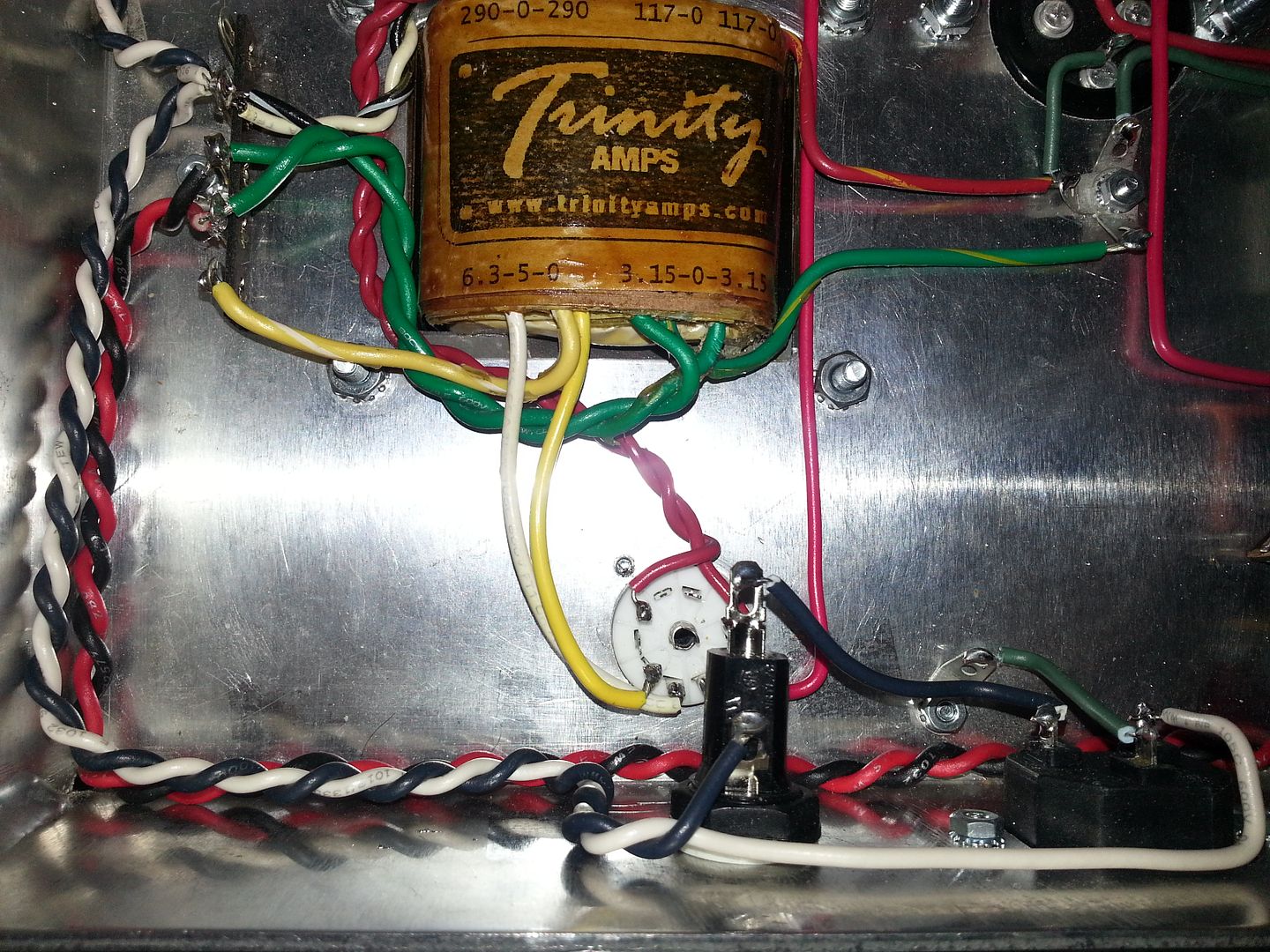
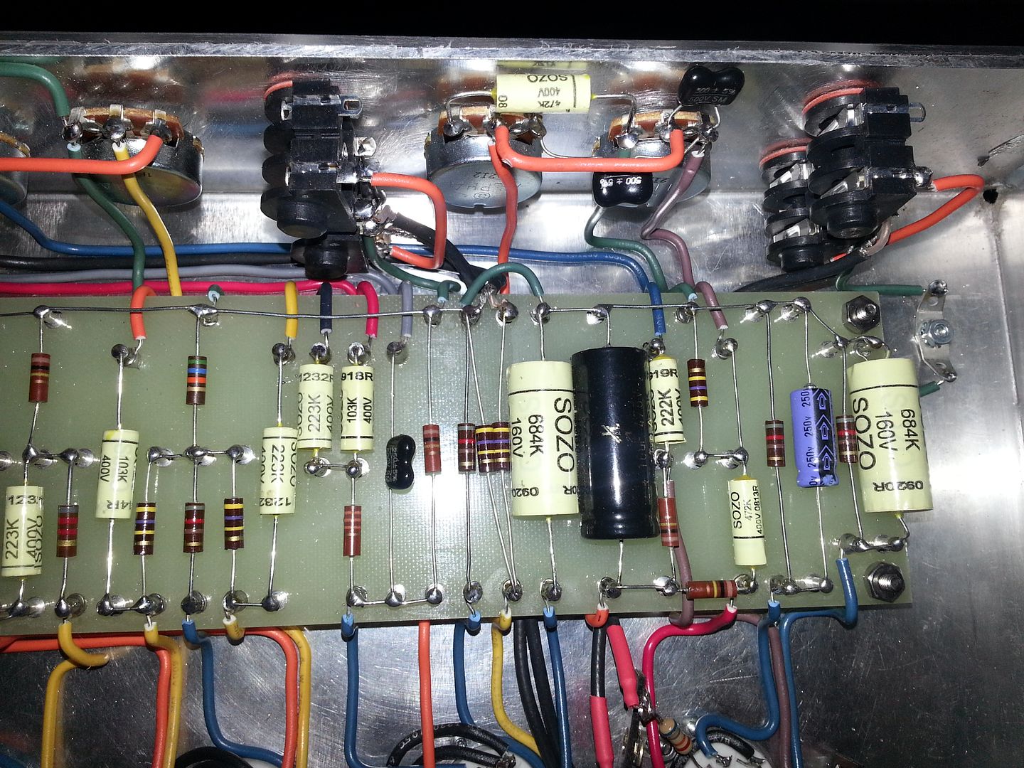
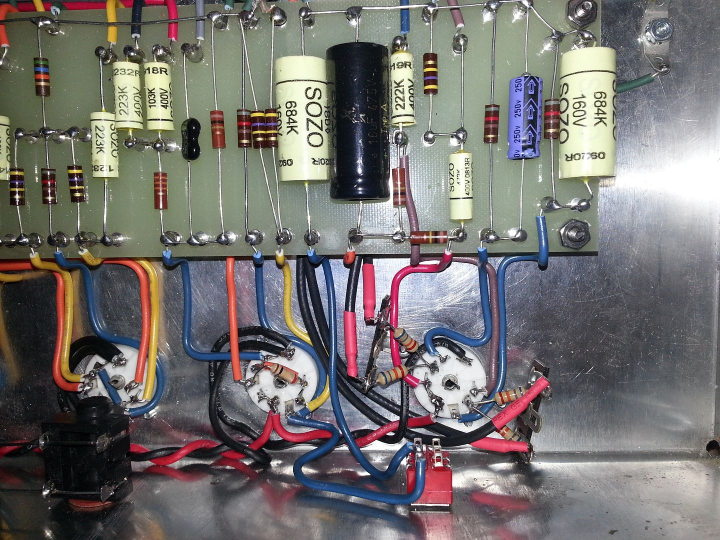
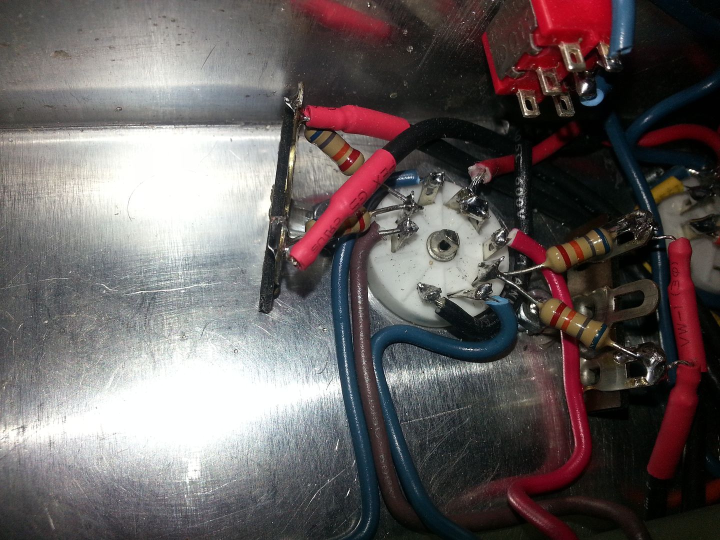
Thank you for the very helpful observations. The three of you were right about the tag strip problem. Just never crossed my mind that the center tab was going to ground. Obvious when pointed out now but I didn't think about it as I was following the layout. Glad you guys caught it because I don't know how long it would have taken me. Here's a better picture of the before and one of the corrected after.
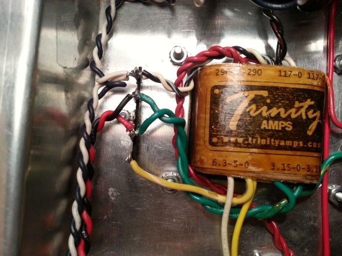
Image

After
Image

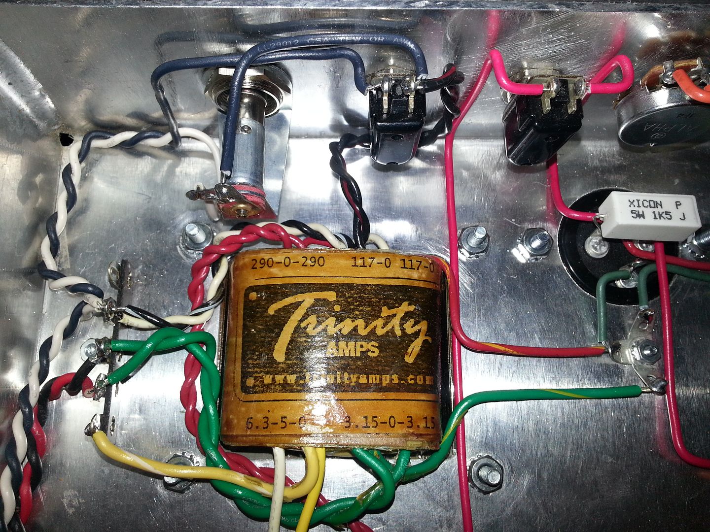
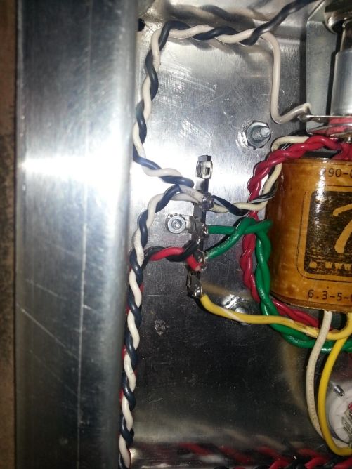
Stephen was also right about the 6.3v indicator. The original Marshall style lamp I ordered from Tubedepot was also a 6.3v. At the last minute I decided to replace it with a Fender style indicator I had laying around. I think I forgot about the two being 6.3v and just thought I was substituting a similar lamp from a Trinity kit with an equally valued Fender style so I just followed the layout as normal. Bad assumption.

So this morning I replaced the Fender style with with a 120v indicator. Started up the amp and at first things went great. Light went on, no hint of burning electronics--so far so good. I start checking voltages--AC Mains 120 (Good), B+ 355 (Good). I turn the amp off and installed the rectifier and fire it up again and start by checking pin 1 of V1. The number I come away with was 150 and again I'm happy. But this is where things got weird. After a couple of seconds the number started to drop. Maybe about a couple digits per second. After about 10 seconds I decided to shut the amp off. After waiting a few minutes I start the amp again--the indicator lights up but now a little dimmer and now get no reading from B+ or pin 1 of V1. The only other readings I'm getting is still 120 for AC mains and 328 on pins 1 and 7 of the rectifier. Anyone have thoughts on why such a thing could happen?


Top
 Profile  
 
PostPosted: Sat Jan 11, 2014 12:25 pm 
Offline
Expert
Expert
User avatar

Joined: Sun Feb 17, 2008 4:47 pm
Posts: 960
Location: Toronto, Canada.
If you take all the tubes out but the rectifier tube does the voltage still drop?

_________________
http://pdfelectronics.com


Top
 Profile  
 
PostPosted: Sat Jan 11, 2014 11:51 pm 
Offline
Friend
Friend

Joined: Sun Nov 21, 2010 3:58 pm
Posts: 19
kurtlives wrote:
If you take all the tubes out but the rectifier tube does the voltage still drop?


The rectifier was the only tube installed when the voltage dropped initially. I thought that the power up procedures recommended in the build guide called for installing the rectifier alone and testing the plate voltages and if those were within acceptable range to then install the preamp and power tubes. Do you think I should install all of the tubes and check the voltages?


Top
 Profile  
 
PostPosted: Tue Jan 14, 2014 6:46 pm 
Offline
Experienced
Experienced
User avatar

Joined: Wed Aug 26, 2009 11:27 pm
Posts: 273
Location: Ontario
From the picture's it looks like pins 4,5,6 on v1 are all wired together but that could be just the picture

And after you powerd back up after the fix you had 6.3v ac at all heaters ? before installing tubes


Top
 Profile  
 
PostPosted: Wed Jan 15, 2014 1:02 pm 
Offline
Friend
Friend

Joined: Sun Nov 21, 2010 3:58 pm
Posts: 19
sazafraz wrote:
From the picture's it looks like pins 4,5,6 on v1 are all wired together but that could be just the picture


I see what you're taking about from the picture but no pin six is not connected. (4 and 5 are). Here's a better picture.

Image

sazafraz wrote:
And after you powerd back up after the fix you had 6.3v ac at all heaters ? before installing tubes


Yes


Top
 Profile  
 
PostPosted: Thu Jan 16, 2014 5:46 pm 
Offline
Experienced
Experienced
User avatar

Joined: Wed Aug 26, 2009 11:27 pm
Posts: 273
Location: Ontario
Looks like every thing is wired up right. The only thing I could suggest at this point is separate the board from the power supply. to see if its come from one side or the other.

Disconnect both red wires from the cap can. put in the rectifier tube only and see if you can get a stable voltage on both sides of the cap can you leave the resistor on it.

If that works add back the red wire to the output transformer and see if you can get a stable voltage at the cap can points and than plate pins on the the output tubes sockets .

If that all is fine then something is loading it on the board. ( check continuity for your jumpers under the board )


Top
 Profile  
 
PostPosted: Thu Jan 16, 2014 5:54 pm 
Offline
Experienced
Experienced
User avatar

Joined: Wed Aug 26, 2009 11:27 pm
Posts: 273
Location: Ontario
Oh and by the way you missing the jumper from pin 3 of one of the output tube socket to the other (so that they share the cathode resistor and cap)


Top
 Profile  
 
PostPosted: Sat Jan 18, 2014 10:05 am 
Offline
Holy Ghost
Holy Ghost
User avatar

Joined: Sun Mar 13, 2005 4:10 pm
Posts: 7519
Location: Canada
Test the rectifier tube ideally with no board hooked up. Test the AC voltages to it and DC from it.

_________________
Stephen
Web: www.trinityamps.com. Facebook: facebook.com/trinityamps. Twitter: @trinityamps


Top
 Profile  
 
PostPosted: Sat Jan 25, 2014 11:48 pm 
Offline
Friend
Friend

Joined: Sun Nov 21, 2010 3:58 pm
Posts: 19
Some home remodeling kept me away from the amp for a while. Before anyone posted their replies after my last comment I tried a new EZ81. When I checked B+ it was off the charts in the 800s range. I put the original EZ81 back in and had the same high voltage result at B+. All I had done was swap out the the indicator for a new 120 volt. With this new problem I didn't try any of the recent recommendations by Stephen and Sazafraz other than connect that jumper on pin 3 between the output tubes. Any help with why the voltage might be so high. Let me know if anyone wants a picture of something specific.


Top
 Profile  
 
PostPosted: Sun Jan 26, 2014 12:24 am 
Offline
Holy Ghost
Holy Ghost
User avatar

Joined: Sun Mar 13, 2005 4:10 pm
Posts: 7519
Location: Canada
Pull the rectifier and test the AC voltages

_________________
Stephen
Web: www.trinityamps.com. Facebook: facebook.com/trinityamps. Twitter: @trinityamps


Top
 Profile  
 
PostPosted: Sun Jan 26, 2014 2:01 am 
Offline
Friend
Friend

Joined: Sun Nov 21, 2010 3:58 pm
Posts: 19
coco wrote:
Pull the rectifier and test the AC voltages


328 on pins 1 and 7 of V6.


Top
 Profile  
 
PostPosted: Mon Jan 27, 2014 11:17 pm 
Offline
Holy Ghost
Holy Ghost
User avatar

Joined: Sun Mar 13, 2005 4:10 pm
Posts: 7519
Location: Canada
That is good if it's 630 total across the high voltage unloaded.
But What rectifier? A 5AR4 would have the high voltage across pins 4 and 6 not 1&7. Looks like you're using an EZ81.
Anyway, seems like it could be OK and you could look down stream from that.

_________________
Stephen
Web: www.trinityamps.com. Facebook: facebook.com/trinityamps. Twitter: @trinityamps


Top
 Profile  
 
PostPosted: Fri Jan 31, 2014 4:28 pm 
Offline
Friend
Friend

Joined: Sun Nov 21, 2010 3:58 pm
Posts: 19
Sometimes I think I'm too stupid to live. I'm not sure where that high B+ number came from. I tested it again and it was fine. So were all the other voltage numbers so I plugged it into a speaker cab and crossed my fingers. Fire up perfectly! Everything seems to be working, amp is quiet, and it sounds great. I couldn't be happier. I haven't really cranked it up yet. (I'm going to go over tonight and give my neighbors a little warning and then dime the thing). Just like with my TC-15 and Tramp kit builds I'll post some pictures when I build the cab.

Thanks to everyone who helped me get this running.


Top
 Profile  
 
Display posts from previous:  Sort by  
Post new topic Reply to topic  [ 21 posts ]  Go to page 1, 2  Next

All times are UTC - 5 hours [ DST ]


Who is online

Users browsing this forum: No registered users and 16 guests


You cannot post new topics in this forum
You cannot reply to topics in this forum
You cannot edit your posts in this forum
You cannot delete your posts in this forum
You cannot post attachments in this forum

Search for:
Jump to:  
Powered by phpBB® Forum Software © phpBB Group