In the
"Trinity v6 Docs" thread in the Resource section, the first layout drawing is for
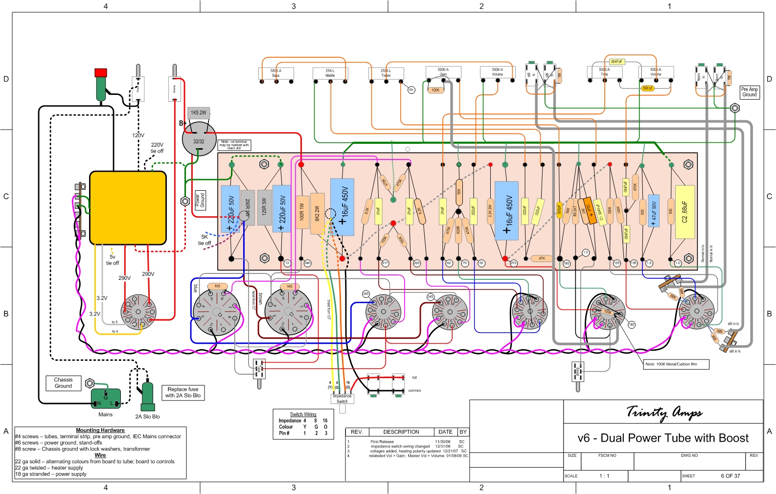
v6 Dual Power with Boost. In the lower right corner of section B1, the sIII in lo and sIII in hi come into V1 together from a little tag board in the corner after going through a pair of 68K resistors.
Do they go to Pin 2, as I suspect, or do they combine with the green wire from the board heading to Pin 3? I just want to be certain for two reasons:
1) just about every other wire leading to a tube pin is drawn heading straight into the center of the pin (i.e. bullseye!), but thesetwo wires sort of take a wide angle to the edge of Pin 2
2) it sure looks like they join that green wire in parallel to Pin 3 on the layout and when I print it out.
http://www.trinityamps.com/ForumGallery ... _21Dec.jpg


