kurtlives wrote:
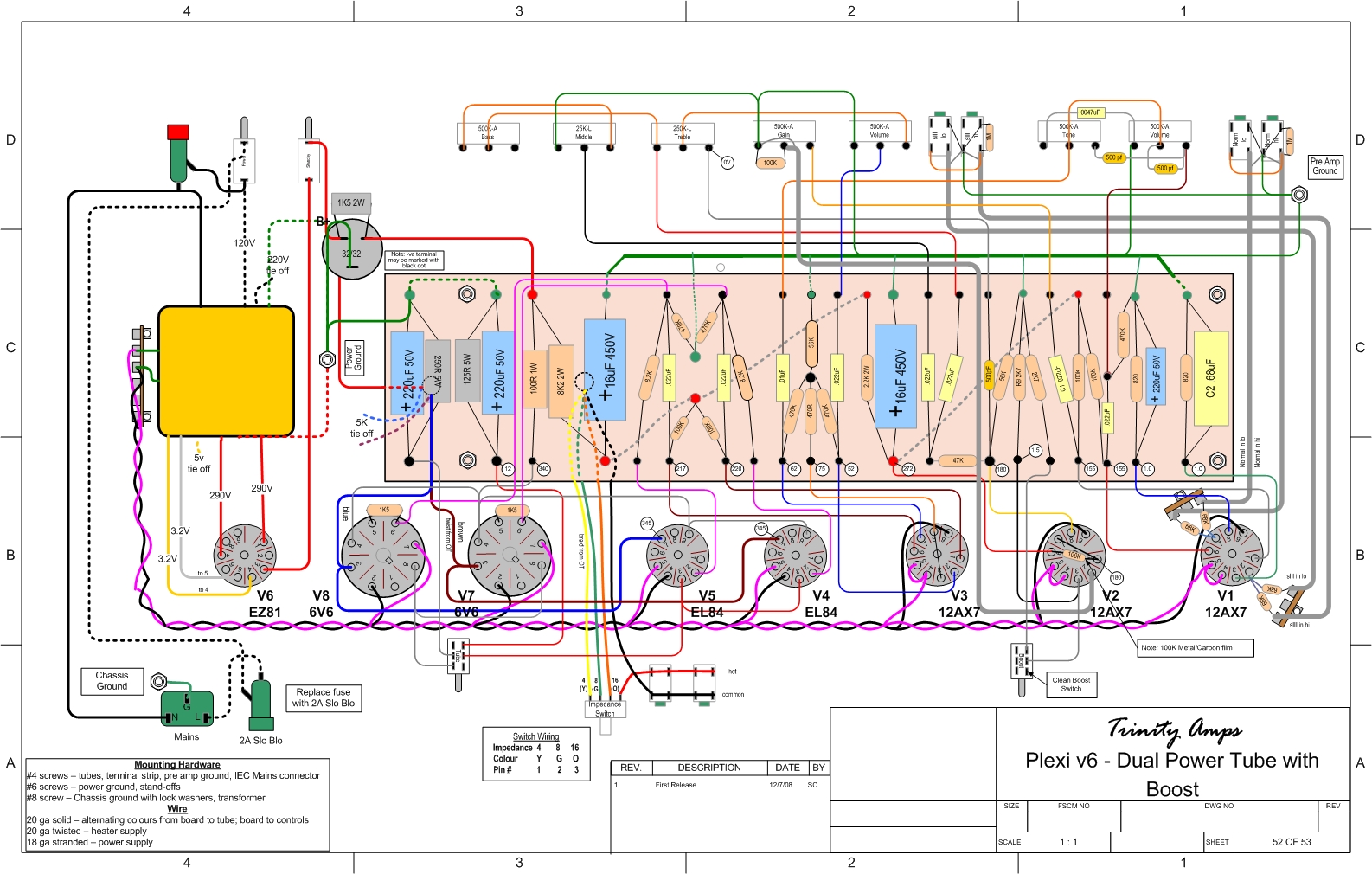
1. The gray wire goes to pin 4 on V7 and V6 and pin 9 on V5 and V4.
2. Post pics so we have reference. Follow the layout and your fine.
3. Email for more wire.
1) First off, you say v6 and v7, but I wrote v7 and v8. I'm guessing that boils down to the layout being weird in that the tube numbers don't go up right to left (rectifier shows up as v6 even though it's at the end and most people would think of it as v8). Bottom line, I hope we are both talking about the 6V6 power tubes. Secondly, I'll have to double check the layout when I get home tonight with regard to v4 and v5. I thought the layout showed pin 8, but you typed pin 9. Definitely need to double-check that.
2) Will do. When I took pictures of last night's progress, I also snapped a few of the layout itself just in case such a question arose. Really need to upload to PhotoBucket, but can't do so until I download to the PC from the camera (C drive currently full pending the wife archiving GOBS of her stuff to the external hard drive, believe it or not!).
3) Thanks, I'll email Trinity.


