trinityamps.com

Trinity Amps Guitar Amp Forum
It is currently Tue Jul 16, 2024 10:33 am

All times are UTC - 5 hours [ DST ]


Post new topic Reply to topic  [ 50 posts ]  Go to page 1, 2, 3  Next
Author Message
PostPosted: Tue Dec 11, 2012 11:03 am 
Offline
Friend
Friend

Joined: Sat Dec 08, 2012 1:27 am
Posts: 40
Hi All,

Just arrived home in Cape Town (South Africa) with my new Tweed kit in my luggage. I'm very excited to start building the amp, it will be my first F-style amp too ;-)

Here it is:
Image

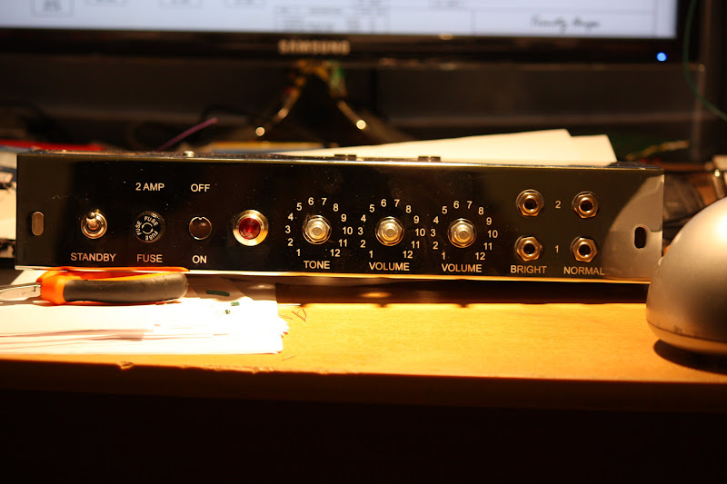
I'm also going to build a cabinet for the Tweed, it will be the first woodwork I do since school (about 15 years ago) so that will likely be trickier. I decided to make my Tweed not a tweed covered amp but to cover it with red tolex and tan + black grill cloth, but I'll use the standard Tweed cabinet design and just substitute the covering material. I've ordered the tweed kit with the VRM module which scales the whole amp I believe. I'm hoping that that will give decent tone to fairly low volumes. The PA/PI scaling on my 18 watt is great in that regard.

I've built an 18 watt amp before so this isn't my first build, I'm hoping this build will go smoothly too (The 18 watt fired up without a hitch first time round). I'm currently also building another 18 watt amp for a friend so that I'll build before I build this kit (I should be done with that in about a week if I get off my butt and do something).

Here's my 18 watt with my two guitars, both are Tokai from Japan. Cabinet contains 2x Celestion G12H30s.
Image

Any hints and tips on how to do a proper sounding 5E3 cabinet will be much appreciated and hints about good looking tolexing around corners will also help me greatly :D

Cheers


Top
 Profile  
 
PostPosted: Tue Dec 11, 2012 8:52 pm 
Offline
Holy Ghost
Holy Ghost
User avatar

Joined: Sun Mar 13, 2005 4:10 pm
Posts: 7519
Location: Canada
Welcome to the brotherhood of Trinity! I sent you cabinet plans and when it comes to tolexing, I can help you as well. Check out the resource section though. A tweed style cab is not the easiest to cover.

_________________
Stephen
Web: www.trinityamps.com. Facebook: facebook.com/trinityamps. Twitter: @trinityamps


Top
 Profile  
 
PostPosted: Fri Dec 14, 2012 1:39 am 
Offline
Friend
Friend

Joined: Thu Aug 23, 2012 12:20 pm
Posts: 12
You wont be disappointed .. i turned mine on with a speaker .. finely .. just a few hours ago im hooked .. wife shut me down something called sleep
it going to be a great Friday . Trinity rocks !!!


Top
 Profile  
 
PostPosted: Wed Dec 19, 2012 8:22 pm 
Offline
Friend
Friend

Joined: Sat Dec 08, 2012 1:27 am
Posts: 40
I have not started yet but I have ordered a BBQ 12A125A, 8ohm, light dope, 30 Watt with a gold basket :D


Top
 Profile  
 
PostPosted: Sat Dec 29, 2012 4:18 pm 
Offline
Friend
Friend
User avatar

Joined: Thu Dec 20, 2012 1:09 am
Posts: 25
Location: Calgary
Keep us posted of your progress; attempting my first build right now (Tweed).

_________________
Muddy
Calgary,AB


Top
 Profile  
 
PostPosted: Mon Jan 07, 2013 5:40 am 
Offline
Friend
Friend

Joined: Sat Dec 08, 2012 1:27 am
Posts: 40
I've recently completed an 18watt build but it has a little problem which I'm trying to remedy before I start my Tweed. Hopefully that will get sorted out soon, I'm itching to start the Tweed.


Top
 Profile  
 
PostPosted: Mon Jan 07, 2013 4:11 pm 
Offline
Holy Ghost
Holy Ghost
User avatar

Joined: Sun Mar 13, 2005 4:10 pm
Posts: 7519
Location: Canada
Maybe we can help you out there too. We do build 18s too!

_________________
Stephen
Web: www.trinityamps.com. Facebook: facebook.com/trinityamps. Twitter: @trinityamps


Top
 Profile  
 
PostPosted: Thu Jan 10, 2013 8:39 am 
Offline
Friend
Friend

Joined: Sat Dec 08, 2012 1:27 am
Posts: 40
I found the issue on the 18 watt. I used a cap rated for 25V between the unused input on the PI to ground. That cap sees more than 50V and the cap didn't like it. Now I must just clean up the mess I made looking for the issue because in the haste I did some bad soldering and there's a really dodgy connection on another coupling cap now. Sigh....


OK back to Tweed stuff. I see there is an old layout and a new layout. Also, I see it is recommended to use the old layout with the VRM. Why is this? I'd like to use the best layout (read minimum hum) because I don't play my amps clean and I don't want hum (not too much at any rate).

I see the VRM came with a little silicon washer. (I haven't read the instructions much, I think I know what to do LOL). I use heatsink paste with a mica washer on the other amps and that works fine. Is this silicon pad a good enough heat conductor to let the MOSFET cool through the chassis?

Do I use the silicon (maybe its not silicon) pad instead of the mica washer + heatsink paste?


Top
 Profile  
 
PostPosted: Thu Jan 10, 2013 12:23 pm 
Offline
Holy Ghost
Holy Ghost
User avatar

Joined: Sun Mar 13, 2005 4:10 pm
Posts: 7519
Location: Canada
Quote:
OK back to Tweed stuff. I see there is an old layout and a new layout. Also, I see it is recommended to use the old layout with the VRM. Why is this? I'd like to use the best layout (read minimum hum) because I don't play my amps clean and I don't want hum (not too much at any rate).

Use the layout provided in the kit. If you have a black board, use the new; a red board; use the old.

Quote:
I see the VRM came with a little silicon washer. (I haven't read the instructions much, I think I know what to do LOL). I use heatsink paste with a mica washer on the other amps and that works fine. Is this silicon pad a good enough heat conductor to let the MOSFET cool through the chassis?
Do I use the silicon (maybe its not silicon) pad instead of the mica washer + heatsink paste?

Use the grey sil pad - use NO paste. it is an electrical insulating, conductive pad..

_________________
Stephen
Web: www.trinityamps.com. Facebook: facebook.com/trinityamps. Twitter: @trinityamps


Top
 Profile  
 
PostPosted: Mon Jan 14, 2013 8:05 pm 
Offline
Friend
Friend

Joined: Sat Dec 08, 2012 1:27 am
Posts: 40
OK so I found someone else to make my cabinet. They're not charging an arm and a leg and do real good work (played on his JTM45 O_o)

Here's what I've done so far..

Image

Image

Image

More to follow soon...


Top
 Profile  
 
PostPosted: Mon Jan 14, 2013 8:31 pm 
Offline
Experienced
Experienced

Joined: Sun Dec 11, 2011 2:00 am
Posts: 188
Location: A Land Downunder
Looks good, nice clean work on the board.

Snowy


Top
 Profile  
 
PostPosted: Tue Jan 15, 2013 12:16 am 
Offline
Holy Ghost
Holy Ghost
User avatar

Joined: Sun Mar 13, 2005 4:10 pm
Posts: 7519
Location: Canada
Did I post pics of a tweed with VRM? IF not, I have some that will Help you.

_________________
Stephen
Web: www.trinityamps.com. Facebook: facebook.com/trinityamps. Twitter: @trinityamps


Top
 Profile  
 
PostPosted: Tue Jan 15, 2013 5:38 am 
Offline
Friend
Friend

Joined: Sat Dec 08, 2012 1:27 am
Posts: 40
I wouldn't mind seeing a very neat VRM installation onto the pot as well as the interconnecting wires so I can figure out a clean layout for that part.

I assume I snip the pot's little solder holes off and solder the legs into the VRM board? (I must get the orientation right, the first two amps I built had the VVR going from loud to soft from 0-10 3rd time lucky I hope)


Top
 Profile  
 
PostPosted: Tue Jan 15, 2013 9:08 am 
Offline
Expert
Expert
User avatar

Joined: Sun Feb 17, 2008 4:47 pm
Posts: 960
Location: Toronto, Canada.
ezietsman wrote:
I wouldn't mind seeing a very neat VRM installation onto the pot as well as the interconnecting wires so I can figure out a clean layout for that part.

I assume I snip the pot's little solder holes off and solder the legs into the VRM board? (I must get the orientation right, the first two amps I built had the VVR going from loud to soft from 0-10 3rd time lucky I hope)

viewtopic.php?f=12&t=1176

Near the bottom of the page. Note this is the old layout so the 0.1uF caps are pot on a terminal strip near the tube socket.

_________________
http://pdfelectronics.com


Top
 Profile  
 
PostPosted: Tue Jan 15, 2013 10:48 am 
Offline
Friend
Friend

Joined: Sat Dec 08, 2012 1:27 am
Posts: 40
Thanks

BTW, the little brown 820 ohm resistor measured 930 Ohm so I replaced it with another one I had lying around. Are those brown ones the carbon composition resistors? They seemed to show gold lines which means 5% but they varied a lot more than the others (more like 10%). Unless I just need a better lamp so I can see in the dark :D


Top
 Profile  
 
PostPosted: Wed Jan 16, 2013 12:07 pm 
Offline
Friend
Friend

Joined: Sat Dec 08, 2012 1:27 am
Posts: 40
Question:

I see the VRM module does not contain a plastic insert for the mosfet which means the mosfet's casing will be attached to the chassis via the screw. I thought one should isolate the mosfet from the chassis entirely.


Top
 Profile  
 
PostPosted: Wed Jan 16, 2013 12:23 pm 
Offline
Expert
Expert
User avatar

Joined: Sun Feb 17, 2008 4:47 pm
Posts: 960
Location: Toronto, Canada.
Do not bolt the MOSFET directly to the chassis. This will create shorts, sparks and general pain when the amp is started up.

Your VRM kit should have come with a grey silica pad that goes between the MOSFET and chassis.

_________________
http://pdfelectronics.com


Top
 Profile  
 
PostPosted: Wed Jan 16, 2013 2:28 pm 
Offline
Friend
Friend

Joined: Sat Dec 08, 2012 1:27 am
Posts: 40
kurtlives wrote:
Do not bolt the MOSFET directly to the chassis. This will create shorts, sparks and general pain when the amp is started up.

Your VRM kit should have come with a grey silica pad that goes between the MOSFET and chassis.


That part is clear. Usually I also put a little plastic insert into the screw hole of the mosfet. This keeps the bolt you use to fasten the mosfet with isolated from the mosfet itself (and hence from the chassis/heatsink) It is this plastic insert I do not have.


Top
 Profile  
 
PostPosted: Wed Jan 16, 2013 6:34 pm 
Offline
Friend
Friend

Joined: Sat Dec 08, 2012 1:27 am
Posts: 40
More pics!

Heaters, before I soldered them.
Image

The VVR board now attached to the On/Off Switch / VVR pot
Image


Power Transformer mostly wired, must still install the Mains power to complete this section of the amp.
Image


Rectifier
Image


Top
 Profile  
 
PostPosted: Fri Jan 18, 2013 6:22 am 
Offline
Friend
Friend

Joined: Sat Dec 08, 2012 1:27 am
Posts: 40
OK so I still want some clarification on the mosfet issue. Here's a photo of the mosfet in my 18 watt. It is attached to the chassis, with heatsink paste and a mica washer. There's a little plastic insert that you insert into the mosfet before you insert the bolt. It keeps the bolt electrically isolated from the mosfet and hence the chassis. I did not receive this with my 5E3 kit. My question is, do I need to go and get one or is the mosfet casing supposed to be attached to the chassis?

Image


Top
 Profile  
 
Display posts from previous:  Sort by  
Post new topic Reply to topic  [ 50 posts ]  Go to page 1, 2, 3  Next

All times are UTC - 5 hours [ DST ]


Who is online

Users browsing this forum: No registered users and 9 guests


You cannot post new topics in this forum
You cannot reply to topics in this forum
You cannot edit your posts in this forum
You cannot delete your posts in this forum
You cannot post attachments in this forum

Search for:
Jump to:  
Powered by phpBB® Forum Software © phpBB Group