trinityamps.com

Trinity Amps Guitar Amp Forum
It is currently Sat Nov 23, 2024 4:54 am

All times are UTC - 5 hours [ DST ]


Post new topic Reply to topic  [ 5 posts ] 
Author Message
PostPosted: Sun Aug 26, 2018 11:19 am 
Offline

Joined: Sat Aug 25, 2018 10:04 am
Posts: 6
Hi Guys,

Great forum here and this is my first full build of an amp, looking forward to it. I do have some background in soldering and circuits, but still lots to learn!

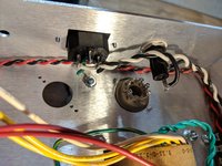
I've just wired up the power transformer, heater wires, power switch, fuse, IEC & light so far and then started to do some continuity checking. Much to my surprise, both heater wires now indicate a short to ground. However, reading through the forum, and confirming what I had thought, is that the heater output windings on the transformer have very little DC resistance and hence why the multimeter would indicate a short. So, I take this reading to be just fine.

My question is in relation to the 120V input taps (Black/red & White/Red) and also the 0 Tap inputs that are wired to the common terminal strip that is fed from the neutral of the IEC plug. With the power switch off, between the 120V taps and the common, I'm showing continuity. It is the same with the power switch on, with the only difference that now the Line & Neutral terminals across the IEC plug also show continuity. Is the same issue with trying to use continuity with low DC resistance elements to confirm proper connections?

I've attached some pics for reference as well.

Cheers,
Tim

Attachment:
IMG_20180826_111422.jpg
IMG_20180826_111422.jpg [ 4.21 MiB | Viewed 6949 times ]

Attachment:
MVIMG_20180826_111433.jpg
MVIMG_20180826_111433.jpg [ 7.14 MiB | Viewed 6949 times ]


Top
 Profile  
 
PostPosted: Tue Aug 28, 2018 9:35 am 
Offline
Holy Ghost
Holy Ghost
User avatar

Joined: Sun Mar 13, 2005 4:10 pm
Posts: 7519
Location: Canada
1. Both heater wires now indicate a short to ground - yes, very little resistance in those windings so normal.
2. 120V common to ground etc. - again, very little resistance in those windings

If you want to be 100% confident, unscrew the grounds lugs from the chassis and re-measure.

_________________
Stephen
Web: www.trinityamps.com. Facebook: facebook.com/trinityamps. Twitter: @trinityamps


Top
 Profile  
 
PostPosted: Thu Aug 30, 2018 8:35 am 
Offline

Joined: Sat Aug 25, 2018 10:04 am
Posts: 6
Thanks Steven. This has confirmed my thoughts.

On a other note, do you have any recommendations for the location and orientation of the optional Choke?
Cheers,
Tim


Top
 Profile  
 
PostPosted: Thu Aug 30, 2018 8:37 am 
Offline

Joined: Sat Aug 25, 2018 10:04 am
Posts: 6
Whoops, maybe I'll move this to a new topic....


Top
 Profile  
 
PostPosted: Sat Sep 01, 2018 2:32 pm 
Offline
Holy Ghost
Holy Ghost
User avatar

Joined: Sun Mar 13, 2005 4:10 pm
Posts: 7519
Location: Canada
The optional choke can go midway between the PT & OT, just inboard of the 32/32 can filter cap.

_________________
Stephen
Web: www.trinityamps.com. Facebook: facebook.com/trinityamps. Twitter: @trinityamps


Top
 Profile  
 
Display posts from previous:  Sort by  
Post new topic Reply to topic  [ 5 posts ] 

All times are UTC - 5 hours [ DST ]


Who is online

Users browsing this forum: No registered users and 25 guests


You cannot post new topics in this forum
You cannot reply to topics in this forum
You cannot edit your posts in this forum
You cannot delete your posts in this forum
You cannot post attachments in this forum

Search for:
Jump to:  
Powered by phpBB® Forum Software © phpBB Group