 |
|
||||||||||||||||||||||||||||||||||||||||||||||||||||||||||

(Page 2 of 3)About The Power Amplifier SectionThis amplifier is cathode biased and operates mostly in a "Class A" mode. This means that current flows continuously through the output tubes whether a signal is present or not. Most amplifier designs employ the more popular "AB" or "AB1" biasing technique, which although capable of producing more power for a given tube configuration and transformer size, produces crossover distortion and more odd order harmonics. This is why the Lightning is described as having a smooth tone that won't fatigue the ears even at high volume.
I learned a lot about building this amp. Here are some tips.
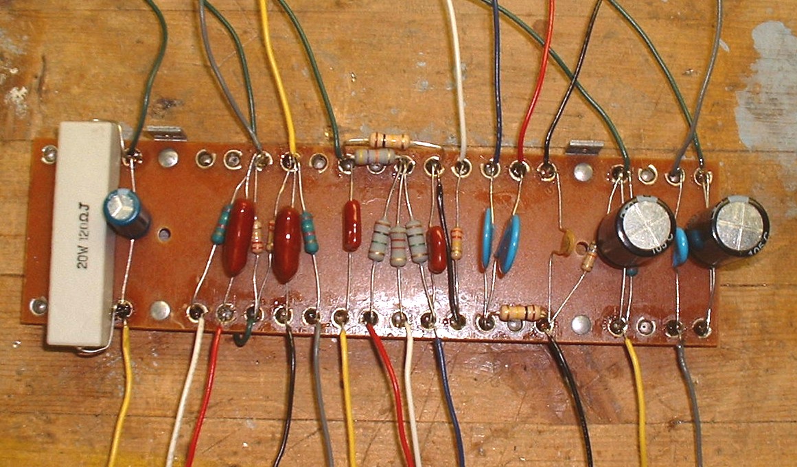
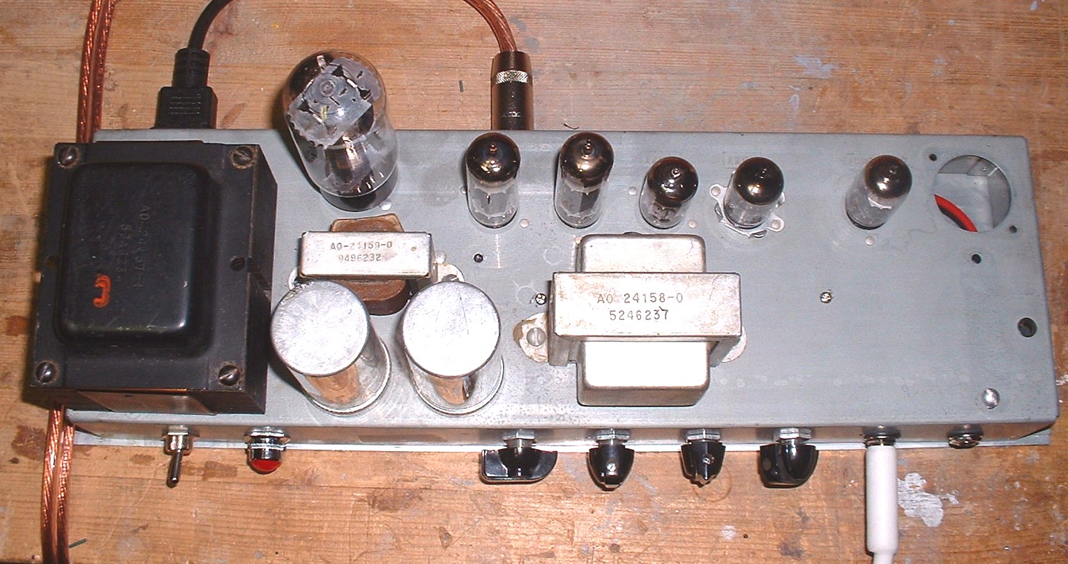
Very Important Construction Tips (lessons learned)To minimize AC hum, here's what worked for me: A) Two star grounding points.
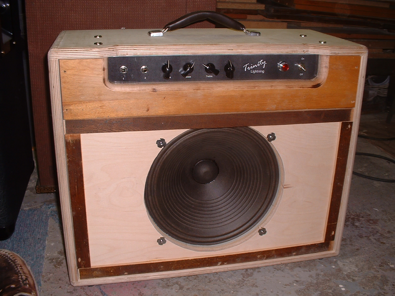
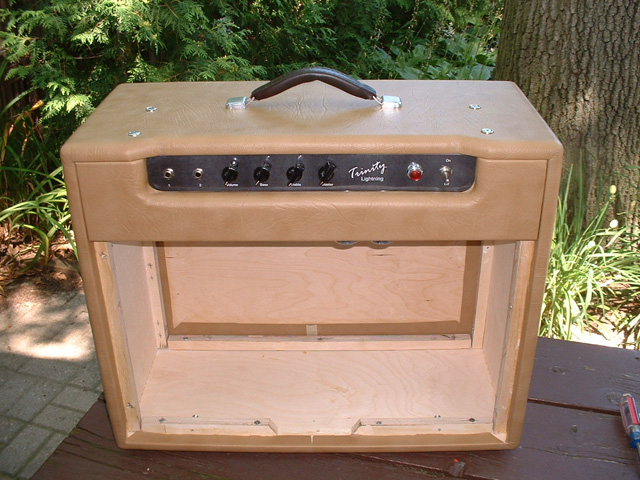
The two star ground points were located at opposite ends of the board. The preamp one, was located beside the input jacks. B) Used a 14H, 50 mA choke instead of a resistor. Some people say "just use a resistor instead of a choke", but in my case, a choke was absolutely necessary. So follow the schematic, there's a reason it was designed that way. C) Electrically isolate the input and output jacks from the chassis using shoulder washers. D) Make sure there is clear and good separation of the OT leads. The output leads go around the 'power' end of the board. The OT input leads go directly to the OT from the EL84s, via underneath the board. The output leads go to the speaker jack which is also electrically isolated from the chassis. E) Twist all AC wires (heaters, power leads, HV AC and switch leads.) Kept them all at the opposite end of the chassis and tight to any iron. F) Tube Heaters were wired in parallel, from tube to tube. G) All power leads went along the 'rear' of the chassis and resistors from tag strips went directly to the tube pins. H) Used shielded cable from the input jack to the tube. Grounded it to the chassis at only one end - beside the tube it was attached to. I) Steel chassis approx size 16" X 5"X 2" with bottom cover. J) I used an 8K output transformer from the donor amp. Sounded good to me - goes from Clean to Dirty, but maybe I'll try a 4K OT some day. Results: With no input connected, this has resulted in a Lightning design, with almost NO hum. CabinetI got the basic design and some good advice from John Irvine. I altered the design only slightly. To build the cabinet, I used 3 / 4 in Russian Birch for the perimeter and the front panel and 1 / 4 in Russian Birch for the baffle and rear panels. I got this at Home Depot. The narrow piece in front of the amp is 3 / 4 in as well. All the joints were 1 / 4 in finger jointed using a home built jig and table saw. I installed 1 / 4 in X 1 in strips around the perimeter of the baffle to raise up the grill cloth off it. Cleats to attach the front and rear panels were ¾ in square pine. I rounded off all the corners with a 1 / 2 in radius router bit.
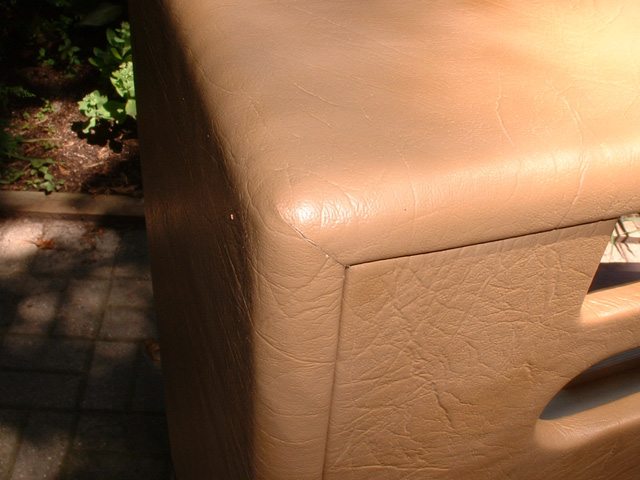
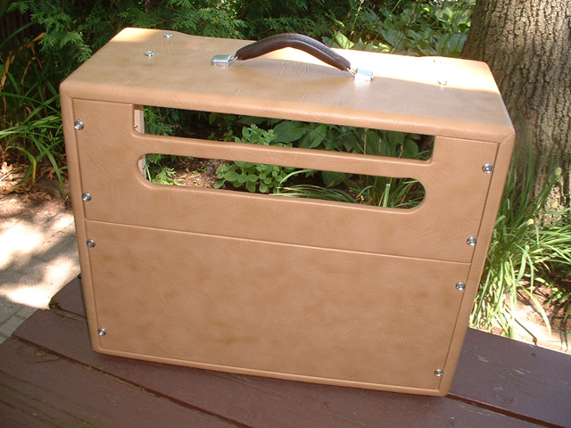
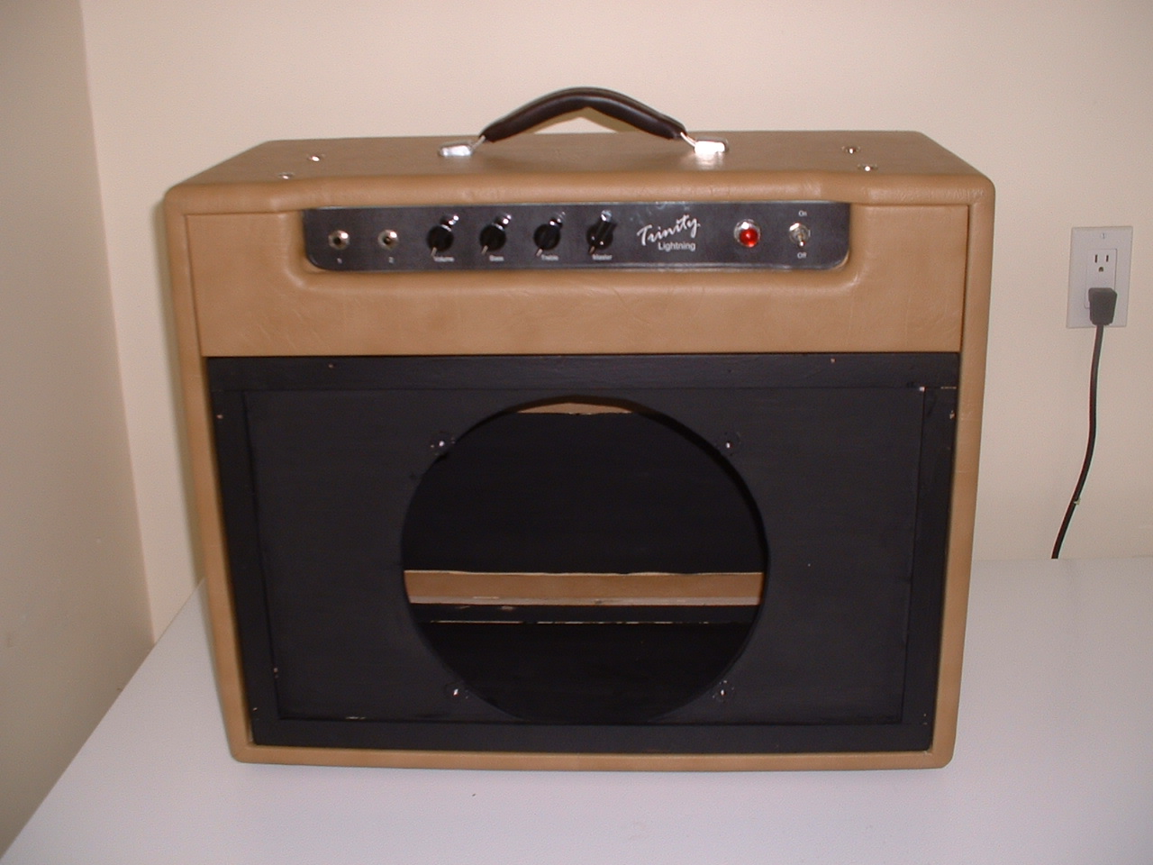
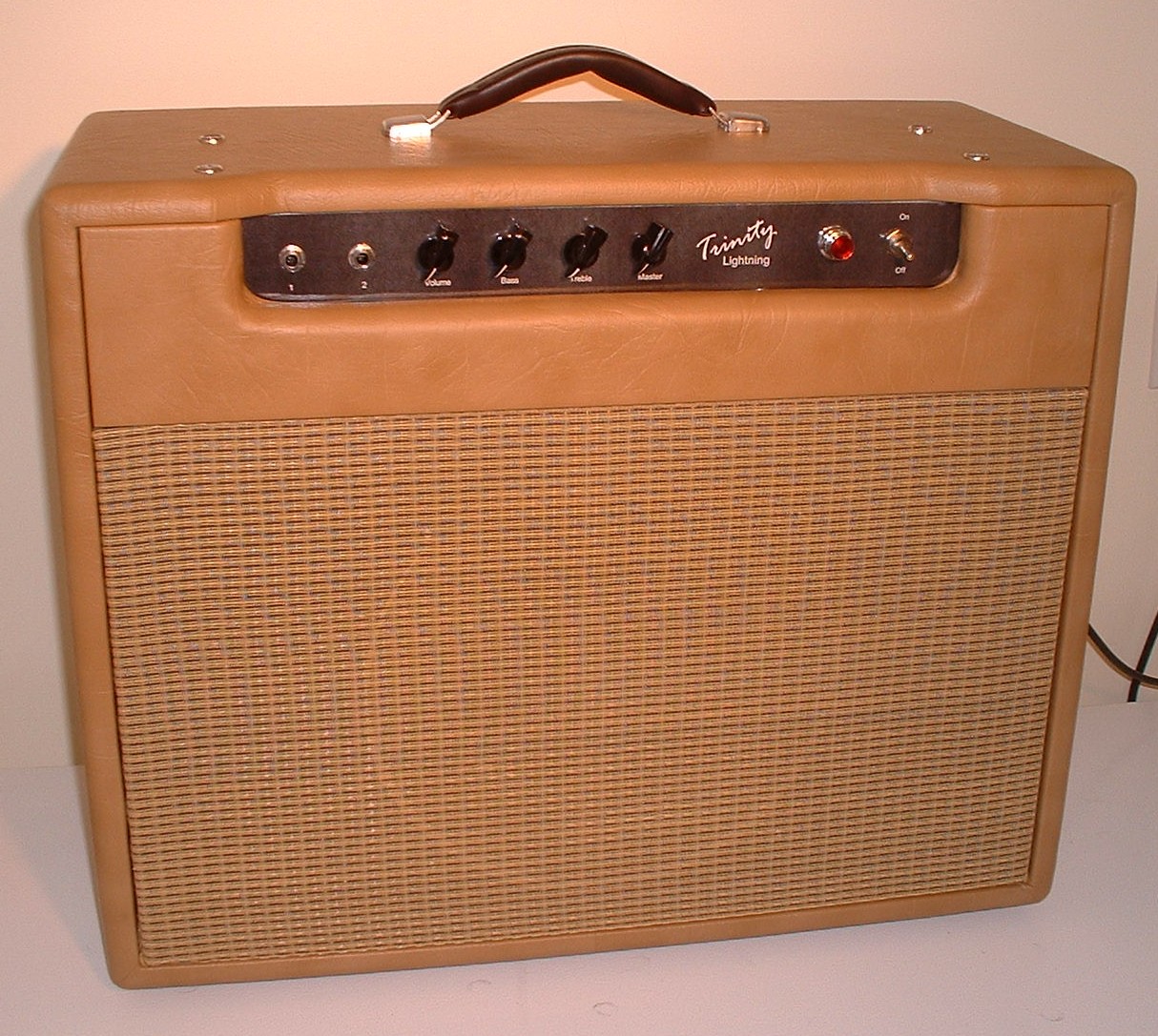
You can cover this with anything you like. I used Tan Tolex for this version. I got some white piping free from an auto upholstery place I might use. Covering a cabinet with Tolex is quite a challenge so learn as much as possible before you undertake it. Here are some pics during the covering process. The handle came from an old portable computer and the feet from a project that was not required anymore. I have some black metal corners I may use when I finish the covering.
|


© 2004/2005 Trinity Amps