trinityamps.com

Trinity Amps Guitar Amp Forum
It is currently Wed Jul 17, 2024 3:28 am

All times are UTC - 5 hours [ DST ]


Post new topic Reply to topic  [ 10 posts ] 
Author Message
 Post subject: TC15 Help Needed
PostPosted: Sat Sep 06, 2008 9:31 pm 
Offline
Friend
Friend

Joined: Tue Aug 12, 2008 8:34 am
Posts: 24
Location: Maryland USA
I just finished my TC15 build and I have a problem.

Channel 1 is working fine. Channel 2 if I turn the volume all the way up I can just barely hear it.

I have rechecked the wiring and everything is connected correctly. I also rechecked all the solder joints to be sure that they are have a good electrical path.

My voltage reading are as follows,

Tube---------Pin1--2----3----4---5---6---7----8-----9
V1------------141-------1.27---------141-----1.27-----(12ax7)
V2------------236-------1.76---------233-----236------(12ax7)
V3------------248--------65----------246------65-------(12ax7)
V4------------------------7.5---------------358-----------(EL84)
V5------------------------7.5---------------353-----------(EL84)
V6------------------------------------------------366------(5AR4)
V7------------81---------1.86---------97-----1.86-------(EF86)

Thanks, Chuck 

 
http://s304.photobucket.com/albums/nn18 ... 658000.jpg

http://s304.photobucket.com/albums/nn18 ... 748874.jpg


Top
 Profile  
 
 Post subject:
PostPosted: Sat Sep 06, 2008 10:40 pm 
Offline
Friend
Friend

Joined: Tue Jul 01, 2008 9:09 am
Posts: 41
Location: NY
The mistake I made was overheating the coax cable from the pot to the grid either when I soldered or when I heated the heat shrink. I got a short from the shield to the conductor. Might be worth a look.


Top
 Profile  
 
 Post subject:
PostPosted: Sun Sep 07, 2008 5:43 am 
Offline
Friend
Friend

Joined: Sun Aug 17, 2008 10:51 am
Posts: 15
Location: Spain
Hi
I had the same problem in channel 1. The problem was a bad solder in the cable that goes from contour pot to Ef86.
Apparently it was ok, but when unsoldered and resoldered it suddenly worked perfect.


Top
 Profile  
 
 Post subject:
PostPosted: Sun Sep 07, 2008 8:39 am 
Offline
Holy Ghost
Holy Ghost
User avatar

Joined: Sun Mar 13, 2005 4:10 pm
Posts: 7519
Location: Canada
Voltages as measured by dtonjes seem to be pretty close to yours although V2 is a little off. Measure your resistor values around Channel 2 circuit as well although they look OK.

AC Mains Voltage is 123VAC ; All tubes are JJ Electronic


Image

Jumper between 100K & 220K under the board [in treble circuit]?

_________________
Stephen
Web: www.trinityamps.com. Facebook: facebook.com/trinityamps. Twitter: @trinityamps


Top
 Profile  
 
 Post subject:
PostPosted: Sun Sep 07, 2008 12:03 pm 
Offline
Friend
Friend

Joined: Tue Aug 12, 2008 8:34 am
Posts: 24
Location: Maryland USA
Here's some of the things I have done.

Checked all the jumpers under the board. Coco, the 220K to 100k jumper is connected.

Checked all the resistor values to be sure they are they are located in the proper position.

Re-checked all the leads to and from the tubes and to the control pots.

Re-soldered all the connections on the eyelet board.

Replaced V1 and V2 with other 12ax7 tubes.

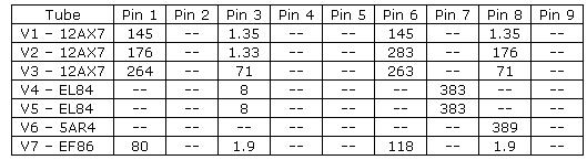
I also re-checked my voltages. They were are about the same as the ones posted above.

Im rather sure this is something simple but what could it be?

What are the possibilities that I may have damaged a part when soldering it in. I am only using a Weller soldering station 25 watt iron with the temp control at 4. (It goes from 1 to 5)

Also, channel 1 is working so I was playing through it for several minutes.

The different setting on the contour switch don't change the tone much. Is this correct? If not, could something here be affecting channel 2 somehow?

I would think that it wouldn't but this problem has really got me stumped. :x


Top
 Profile  
 
 Post subject:
PostPosted: Sun Sep 07, 2008 2:16 pm 
Offline
Holy Ghost
Holy Ghost
User avatar

Joined: Sun Mar 13, 2005 4:10 pm
Posts: 7519
Location: Canada
Chances of damage due to slodering are low in your case.

Try to confirm you have signal to that channel, pin 2. The two channels are independent until the Phase Inverter. If you have signal try this from RG Keen:

Bad preamp cathode resistor
An unbypassed cathode resistor has drifted upwards (to 5K-10K or over)

Faulty phase inverter
If for some reason the phase inverter input side is good but the inverted side is bad, the power amp will still work, but power will be very low. This can be a bad 1/2 tube, a faulty socket contact, a broken or open plate resistor or coupling capacitor to the output tube, or a bad solder joint on any of these.

Open cathode bypass capacitors in preamp
if they go open, the stage they're in loses gain, but does not otherwise fail. If they short, it dramatically shifts the bias point, and may cause distortion as well as low volume.

Is there DC across the Vol, Treble, or Bass Pots?

You might check for that. DC across any pot is usually an indication that a coupling capacitor is leaking, so check for that.

Also, try injecting a signal (a small screwdriver blade for example touching a pin should pop or cause hum) into various places in the signal path to the PI starting at the PI and working toward s the input until the sound stops.

All the tubes light up? And they are making good contact with the socket?

_________________
Stephen
Web: www.trinityamps.com. Facebook: facebook.com/trinityamps. Twitter: @trinityamps


Top
 Profile  
 
 Post subject:
PostPosted: Sun Sep 07, 2008 6:31 pm 
Offline
Holy Ghost
Holy Ghost
User avatar

Joined: Sun Mar 13, 2005 4:10 pm
Posts: 7519
Location: Canada
Quote:
injecting a signal (a small screwdriver blade for example touching a pin should pop or cause hum)


TIP: an insulated alligator clip with a short insulated lead is a good hum injector.

_________________
Stephen
Web: www.trinityamps.com. Facebook: facebook.com/trinityamps. Twitter: @trinityamps


Top
 Profile  
 
 Post subject:
PostPosted: Sat Dec 20, 2008 3:56 pm 
Offline
Holy Ghost
Holy Ghost
User avatar

Joined: Sun Mar 13, 2005 4:10 pm
Posts: 7519
Location: Canada
Amp is fixed. V2 pin 7 was connected to the power supply instead of to pin 6. Everything checks out now.

_________________
Stephen
Web: www.trinityamps.com. Facebook: facebook.com/trinityamps. Twitter: @trinityamps


Top
 Profile  
 
 Post subject:
PostPosted: Sat Dec 20, 2008 11:28 pm 
Offline
Novice
Novice

Joined: Thu Jun 05, 2008 11:39 am
Posts: 60
Location: USA
coco wrote:
Amp is fixed. V2 pin 7 was connected to the power supply instead of to pin 6. Everything checks out now.


Good to hear!

Enjoy! 8)

_________________
Deric®


Top
 Profile  
 
 Post subject:
PostPosted: Thu Feb 12, 2009 11:16 am 
Offline
Friend
Friend

Joined: Tue Aug 12, 2008 8:34 am
Posts: 24
Location: Maryland USA
coco wrote:
Amp is fixed. V2 pin 7 was connected to the power supply instead of to pin 6. Everything checks out now.


I want to thank Coco for his help in solving my problem. I was so mad at myself for not finding this simple mistake. :x

I knew that a fresh set of experienced eyes would help.

Coco did comment that the amp was assembled very neatly. That meant alot to me coming from the TC15 guru himself. :)

Well, I have had the amp back and working about a month now. I wanted to wait until I had time to really try it out and get over the "honeymoon" phase. I really like this amp. It has that voxey tone going that I was looking for. I am currently using the amp with a greenback style speaker, but plan when the funds are available to get a new cabinet with Celestion blue or gold speakers.


Top
 Profile  
 
Display posts from previous:  Sort by  
Post new topic Reply to topic  [ 10 posts ] 

All times are UTC - 5 hours [ DST ]


Who is online

Users browsing this forum: No registered users and 16 guests


You cannot post new topics in this forum
You cannot reply to topics in this forum
You cannot edit your posts in this forum
You cannot delete your posts in this forum
You cannot post attachments in this forum

Search for:
Jump to:  
cron
Powered by phpBB® Forum Software © phpBB Group