trinityamps.com

Trinity Amps Guitar Amp Forum
It is currently Tue Jul 16, 2024 10:20 am

All times are UTC - 5 hours [ DST ]


Post new topic Reply to topic  [ 170 posts ]  Go to page 1, 2, 3, 4, 5 ... 9  Next
Author Message
 Post subject: Plexi Brown Mods
PostPosted: Tue Mar 08, 2011 3:55 am 
Offline
Experienced
Experienced

Joined: Fri Aug 27, 2010 8:57 pm
Posts: 226
Location: Dallas, Tx
Some people have liked the sound of my amp (http://www.unimind.us/TrinityPlexi2.mp3) and asked how they can get their amp to sound like mine so I decided to make a Plexi Brown schematic showing what values to change to get the "Brown" sound. (If, like me, that is what you are after. 8) )

Stephen if this sort of thing is inappropriate or not permitted then I apologize and please delete this post.

DISCLAIMER: USE AT YOUR OWN RISK. THIS INFORMATION IS PROVIDED WITHOUT WARRENTY OF ANY KIND. THE AUTHOR AND TRINITY AMPS EXPRESSLY DISCLAIM ALL LIABILLTY FOR INJURY OR PROPERTY DAMAGE RESULTING FROM THIS INFORMATION!


Thought I would protect myself and Stephen just in case.

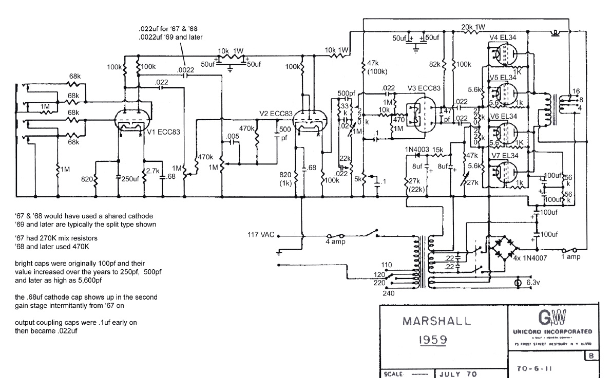
My goal was to take the 1959 Plexi schematic (http://www.unimind.us/images/1959_Plexi_Schematic.jpg) and apply it to an 18 watt amp. Trinity Amps 18 watt Plexi schematic was pretty close already so only minor changes were needed. And then I would throw a little "Brown" tweaks in there for good measure.

Some of these changes are similar to the sIII version so you may want to start with those changes first and see if you like them.
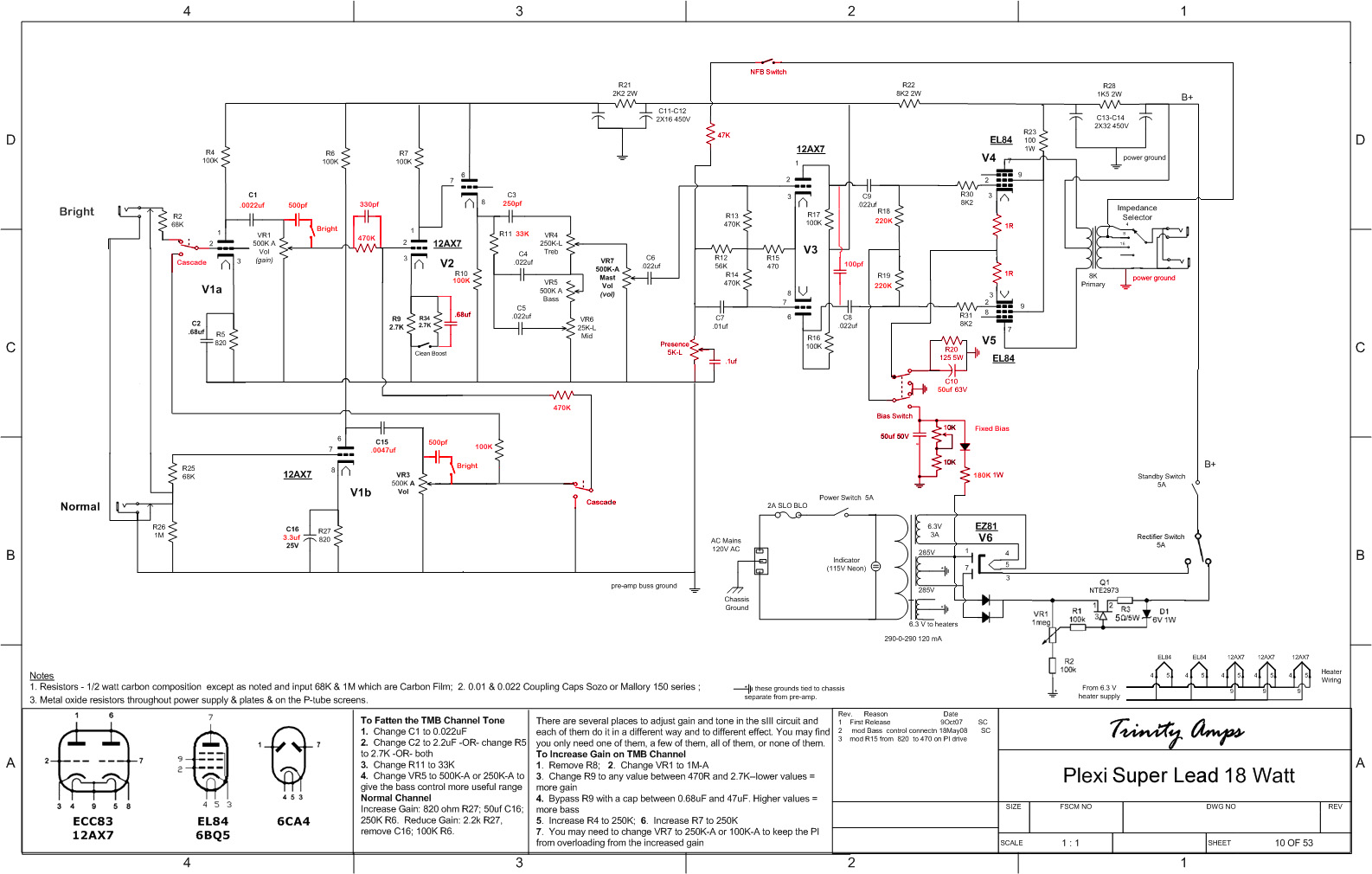
 viewtopic.php?f=12&t=689

Here is the Plexi Brown schematic I put together. (Edit: Removed link. Please see coco's final version later in this thread.)

Experts.. Please chime in and correct me on any of this information.

Starting with C1 - V1a coupling cap. Lowering the value to .0022uF reduces the bass going to the next stage.
Added the V1a mix resistor (or V2a grid stopper) R42 (470K) which reduces gain to V2a.
The mix resistor bypass capacitor C20 will allow certain frequencies to pass. The 1959 value is 500pF(mica). The "Brown" value is 330pF(mica) (less bass).
Changed R8 to 470K. This the normal channel mix resistor in the 1959 circuit and acts as a grid leak to V2a. Also reduces gain to V2a.
Added C21 - V2a cathode bypass capacitor. .68uF reduces the bass and increases gain in V2a.
Increased V2b cathode resistor to 100K reduces gain.
Changed R11 tone stack slope resistor to 33k. Shifts the tone stack frequencies to upper mids.
Changed treble capacitor to 250pF. Another "Brown" value. Increases treble frequencies (or in reality, lowers the bass frequencies).
Check the value of R15. The Plexi value is 470R if you do not have the Plexi version you will need to change this. Lowering this value increases gain in the phase inverter.
Changed C10 - V4/V5 cathode bypass capacitor to 50uF 50V. This lowers the bass in the power tubes.
R18 and R19 - V4/V5 grid leaks. I lowered these to 220k because with fixed bias (which I am using) the maximum value is 330K for EL84s. I chose the 220K because it matched the 1959 circuit. Lower values I believe increase gain. It may shorten the life of the EL84s. Need the experts to chime in on this one.
R30 and R31 - V4/V5 grid stoppers. Again the 1959 circuit has 5.6K there which should increase gain. It may shorten the life of the EL84s. Need the experts for this one as well.

One more tweak that I am thinking of doing is to reduce R9 - V2a cathode resistor and R34 - boost resistor to 1.8K. This will then be 900R when the boost switch is on which closely matches the 1959 circuit value of 820R-1K. This will increase the gain of V2a slightly more.

You may want to add the "Bright Cap" to VR1 volume pot. The 1959 circuit has 500pF for the value. This will allow certain frequencies to pass as the volume pot is reduced. I left it out as most people do because when you have the volume at 10 it does nothing.

So there you have it. The 18 watt Plexi Brown mods. That should get you pretty close to the "Brown" sound. The rest is the guitar, the player, the speakers, the mic, the recording console, the engineer etc. etc. etc. :roll:

I hope this is of value to some of you and again all you experts please correct any of this information as I am definitely not an expert. I have only been learning this stuff over the last 8-12 months and have only built one amp. :bugeye:

-Les

_________________
Les

http://www.soundclick.com/unimind


Last edited by Unimind on Fri Mar 11, 2011 1:42 pm, edited 2 times in total.

Top
 Profile  
 
 Post subject: Re: Plexi Brown Mods
PostPosted: Tue Mar 08, 2011 4:06 pm 
Offline
Expert
Expert
User avatar

Joined: Sun May 20, 2007 1:45 pm
Posts: 1254
Location: YYZ
Awesome!!! :thumbsup:
I will study these mods with great interest.
BTW I don't believe there's any policy at Trinity against modding amps. :D

Unimind wrote:
I have only been learning this stuff over the last 8-12 months and have only built one amp. :bugeye:

:jawdrop: Holy suffering catfish! That's your first ever build???

Here are some comments:
Unimind wrote:
Increased V2b cathode resistor to 100K reduces gain.
Changed R11 tone stack slope resistor to 33k. Shifts the tone stack frequencies to upper mids.

Check the value of R15. The Plexi value is 470K if you do not have the Plexi version you will need to change this. Lowering this value increases gain in the phase inverter.

Changed C10 - V4/V5 cathode bypass capacitor to 50uF 50V. This lowers the bass in the power tubes.

R18 and R19 - V4/V5 grid leaks. I lowered these to 220k because with fixed bias (which I am using) the maximum value is 330K for EL84s. I chose the 220K because it matched the 1959 circuit. Lower values I believe increase gain. It may shorten the life of the EL84s. Need the experts to chime in on this one.

R30 and R31 - V4/V5 grid stoppers. Again the 1959 circuit has 5.6K there which should increase gain. It may shorten the life of the EL84s. Need the experts for this one as well.

One more tweak that I am thinking of doing is to reduce R9 - V2a cathode resistor and R34 - boost resistor to 1.8K. This will then be 900R when the boost switch is on which closely matches the 1959 circuit value of 820R-1K. This will increase the gain of V2a slightly more.


- Changing V2b's cathode resistor has no effect on gain at all. It will just subtly alter how it clips.
- R15 should be 470 ohms, not 470k :)
- Changing the slope resistor R11 to 33k increases mids, and reduces scoop. I also recommend reducing the Mid cap C4 in the tone stack to 0.01uF to give a more useful sweep range on the Bass control.
- Lower values for R18 & 19 decreases drive to the power tubes and overall gain. You will get quite a bit less power amp distortion. It has zero effect on tube lifetime.
- Reducing grid blocking resistors R30 & R31 has zero effect on gain and will just make the amp a little brighter, which IMO isn't needed. Personally I would leave them the way they are. The EL84 design guides actually recommend 10k as the minimum value. I've actually been thinking about trying larger values, like 22k, to smooth the distortion a little more.
- Alternatively increasing C10 to 1000uF or above also tightens bass, and stiffens the feel of the amp at the same time, more like a fixed-bias big Marshall. You said something about also having fixed-bias in your amp, but I can't see it anywhere. With the huge cap, you might want to cool the bias a bit, by increasing cathode resistor R20 to 180 ohms.
- Reducing V2a's cathode resistor only affects gain when the bypass cap isn't there - ie when boost is off.
- The Plexi bright cap gets snipped off by a lot of people, so I suspect it may not be real popular here either...

_________________
Great tones come in small glass jars!


Top
 Profile  
 
 Post subject: Re: Plexi Brown Mods
PostPosted: Tue Mar 08, 2011 11:29 pm 
Offline
Experienced
Experienced

Joined: Fri Aug 27, 2010 8:57 pm
Posts: 226
Location: Dallas, Tx
zaphod, thanks for your comments. As I said I am no expert and don't fully understand all of this. This all comes from my thinking why not build the 1959 plexi circuit with el84s in the power section.

zaphod wrote:
- R15 should be 470 ohms, not 470k :)
That is correct. I will edit my post and correct that.
zaphod wrote:
- Lower values for R18 & 19 decreases drive to the power tubes and overall gain. You will get quite a bit less power amp distortion. It has zero effect on tube lifetime.
- Reducing grid blocking resistors R30 & R31 has zero effect on gain and will just make the amp a little brighter, which IMO isn't needed. Personally I would leave them the way they are. The EL84 design guides actually recommend 10k as the minimum value. I've actually been thinking about trying larger values, like 22k, to smooth the distortion a little more.
This is good to know. I chose those values only because that is what the 1959 circuit has with fixed bias.
zaphod wrote:
You said something about also having fixed-bias in your amp, but I can't see it anywhere.
I left out the fixed-bias here because this was mainly for those that do not have fixed bias and just want to try these mods in their circuit. I also left out the negative feedback loop which I also think helps smooth out the power section. Along with the NFB I also have a 100pF mica (another Brown value) across the PI plates. I read that this tames some of the high end fizz. The 1959 circuit value is 47pF.

-Les

_________________
Les

http://www.soundclick.com/unimind


Top
 Profile  
 
 Post subject: Re: Plexi Brown Mods
PostPosted: Wed Mar 09, 2011 8:58 am 
Offline
Holy Ghost
Holy Ghost
User avatar

Joined: Sun Mar 13, 2005 4:10 pm
Posts: 7519
Location: Canada
I was going to point out that 470R resistor.

Also, note that the plexi kits ship with 220uf/820R on cathode of Normal Channel.

I will study it some more and maybe, together, we can come up with a Trinity Plexi Mk. II.

_________________
Stephen
Web: www.trinityamps.com. Facebook: facebook.com/trinityamps. Twitter: @trinityamps


Top
 Profile  
 
 Post subject: Re: Plexi Brown Mods
PostPosted: Wed Mar 09, 2011 11:38 am 
Offline
Experienced
Experienced

Joined: Fri Aug 27, 2010 8:57 pm
Posts: 226
Location: Dallas, Tx
coco wrote:
Also, note that the plexi kits ship with 220uf/820R on cathode of Normal Channel.
Stephen it seems that in the Plexi docs the layout file has been updated to reflect this but the schematic still shows 47uF.

-Les

_________________
Les

http://www.soundclick.com/unimind


Top
 Profile  
 
 Post subject: Re: Plexi Brown Mods
PostPosted: Wed Mar 09, 2011 2:21 pm 
Offline
Expert
Expert
User avatar

Joined: Sun May 20, 2007 1:45 pm
Posts: 1254
Location: YYZ
Unimind wrote:
I left out the fixed-bias here because this was mainly for those that do not have fixed bias and just want to try these mods in their circuit.

For those running cathode bias, a cathode cap in the 1000uF to 2200uF range will give a cathode-biased amp somewhat more of a fixed bias feel.

Unimind wrote:
I also left out the negative feedback loop which I also think helps smooth out the power section. Along with the NFB I also have a 100pF mica (another Brown value) across the PI plates. I read that this tames some of the high end fizz. The 1959 circuit value is 47pF.

How are you doing the NFB? For NFB to be effective you have to make some fairly major changes to the PI and how the preamp channels are mixed together. If you only apply it to the PI tail it has close to no effect at all. In that case, 99.9% of the effect is from that 100pF across the PI output, as well as the 220k grid reference resistors. I have sometimes used the PI cap trick in my own builds.

_________________
Great tones come in small glass jars!


Top
 Profile  
 
 Post subject: Re: Plexi Brown Mods
PostPosted: Wed Mar 09, 2011 3:46 pm 
Offline
Experienced
Experienced

Joined: Fri Aug 27, 2010 8:57 pm
Posts: 226
Location: Dallas, Tx
zaphod wrote:
How are you doing the NFB? For NFB to be effective you have to make some fairly major changes to the PI and how the preamp channels are mixed together. If you only apply it to the PI tail it has close to no effect at all. In that case, 99.9% of the effect is from that 100pF across the PI output, as well as the 220k grid reference resistors. I have sometimes used the PI cap trick in my own builds.

Here is the schematic for my amp. http://www.unimind.us/images/Trinity18_ ... ematic.jpg
Are there other changes I need to make to the PI? Should I be using the 10k tail and 1M grid leaks from the 1959 circuit as well? I thought they mainly controlled the impendence and since I don't really understand all that yet I thought it best leave that the way it is. :?

The NFB works well as I have it. Takes the harsh edge off the top end. Lowers output a little.

-Les

_________________
Les

http://www.soundclick.com/unimind


Top
 Profile  
 
 Post subject: Re: Plexi Brown Mods
PostPosted: Wed Mar 09, 2011 4:37 pm 
Offline
Expert
Expert
User avatar

Joined: Sun May 20, 2007 1:45 pm
Posts: 1254
Location: YYZ
Yes, the way you're applying the NFB to the PI tail means it's having very little actual effect apart from removing a little fizziness. However, that seems to be a worthwhile improvement. In a true 1959 or 1987, the two preamp channels are mixed at the second preamp stage and the NFB is then applied tp the "B" input of the PI, which has a much more massive effect. In the case of your 18W, that would tend to make the amp feel less lively.

You absolutely don't want a 10k tail resistor in the PI, as your EL84s will start to crap out with the excessive drive from the PI. The 15k (10k+5k pot) tail resistor value is meant for driving much lower gain octal power tubes. I would however say that the regular value for a Marshall 18W or Vox/Matchless tail resistor is 47k. What you have right now is effectively 56k+5k = 61k, so you aren't really providing much drive to the EL84s, and even more so given the low value 220k grid reference resistors. So I would suggest changing your fixed tail resistor to something in the 9k to 47k range to allow the EL84s to work a little more. The 1M or 470k reference resistors make on the PI make virtually no difference either way.

I have to say I'm real excited about what you've done here. :D

_________________
Great tones come in small glass jars!


Top
 Profile  
 
 Post subject: Re: Plexi Brown Mods
PostPosted: Wed Mar 09, 2011 7:05 pm 
Offline
Experienced
Experienced

Joined: Fri Aug 27, 2010 8:57 pm
Posts: 226
Location: Dallas, Tx
zaphod wrote:
Yes, the way you're applying the NFB to the PI tail means it's having very little actual effect apart from removing a little fizziness. However, that seems to be a worthwhile improvement. In a true 1959 or 1987, the two preamp channels are mixed at the second preamp stage and the NFB is then applied tp the "B" input of the PI, which has a much more massive effect. In the case of your 18W, that would tend to make the amp feel less lively.
You should see in my schematic that I do mix the channels at the second stage and the NFB does connect to the tail and second PI input.
zaphod wrote:
You absolutely don't want a 10k tail resistor in the PI, as your EL84s will start to crap out with the excessive drive from the PI. The 15k (10k+5k pot) tail resistor value is meant for driving much lower gain octal power tubes. I would however say that the regular value for a Marshall 18W or Vox/Matchless tail resistor is 47k. What you have right now is effectively 56k+5k = 61k, so you aren't really providing much drive to the EL84s, and even more so given the low value 220k grid reference resistors. So I would suggest changing your fixed tail resistor to something in the 9k to 47k range to allow the EL84s to work a little more. The 1M or 470k reference resistors make on the PI make virtually no difference either way.
Thanks for this. I have been trying to research this but there is very little information on NFB in 18 watt designs. There are a few schematics over at 18watt dot com but little information as to how they came up with the values. I think I just usally see 47k on the tail. I had picked up resistors of various values to try there (47K, 33K, 22K and 15K) but I wanted to understand a little more what I was doing so I didn't blow something up. The other reason I left it alone was I have the NFB on a switch and didn't want things out of wack when the NFB is switched off.
zaphod wrote:
I have to say I'm real excited about what you've done here. :D
Thanks for all your input. I think things might have been easier if I just built a straight up Super Lead 18 without all the switches and without cascade etc. but I like having all the options. Just makes things a little more tricky when working with the circuit because you have to keep in mind that the switch can be turned off. :)

_________________
Les

http://www.soundclick.com/unimind


Top
 Profile  
 
 Post subject: Re: Plexi Brown Mods
PostPosted: Wed Mar 09, 2011 7:33 pm 
Offline
Holy Ghost
Holy Ghost
User avatar

Joined: Sun Mar 13, 2005 4:10 pm
Posts: 7519
Location: Canada
Quote:
I think things might have been easier if I just built a straight up Super Lead 18 without all the switches and without cascade etc.

Why dont we see if we can settle on a schematic exactly for that & maybe it can be the Mk. II

_________________
Stephen
Web: www.trinityamps.com. Facebook: facebook.com/trinityamps. Twitter: @trinityamps


Top
 Profile  
 
 Post subject: Re: Plexi Brown Mods
PostPosted: Wed Mar 09, 2011 9:00 pm 
Offline
Experienced
Experienced

Joined: Fri Aug 27, 2010 8:57 pm
Posts: 226
Location: Dallas, Tx
coco wrote:
... maybe it can be the Mk. II
With your's and Phil's expertise maybe we can nail it pretty good. How far would you want to go with it i.e. SS recto, NFB, fixed bias, presence control etc. all standard in the design?

-Les

_________________
Les

http://www.soundclick.com/unimind


Top
 Profile  
 
 Post subject: Re: Plexi Brown Mods
PostPosted: Wed Mar 09, 2011 10:52 pm 
Offline
Holy Ghost
Holy Ghost
User avatar

Joined: Sun Mar 13, 2005 4:10 pm
Posts: 7519
Location: Canada
It would have to fit the formate of the current chassis, turret board. There is one extra hole in the back that could be used for NFB if it was useful (could be a builder tweak). No SS recto, fixed bias, or presence control. Just what's necessary to capture the tone.

_________________
Stephen
Web: www.trinityamps.com. Facebook: facebook.com/trinityamps. Twitter: @trinityamps


Top
 Profile  
 
 Post subject: Re: Plexi Brown Mods
PostPosted: Wed Mar 09, 2011 10:59 pm 
Offline
Experienced
Experienced

Joined: Fri Aug 27, 2010 8:57 pm
Posts: 226
Location: Dallas, Tx
So for the preamp side of things that would be what I posted at the start of this thread. I am still not sure about the poweramp side i.e. grid reference and stoppers. We will need someone to try the above "brown" schematic and see how it works. Maybe also add the 100pF on the PI plates to tame the fizz a little.

_________________
Les

http://www.soundclick.com/unimind


Top
 Profile  
 
 Post subject: Re: Plexi Brown Mods
PostPosted: Thu Mar 10, 2011 1:27 am 
Offline
Expert
Expert
User avatar

Joined: Sun May 20, 2007 1:45 pm
Posts: 1254
Location: YYZ
Unimind wrote:
You should see in my schematic that I do mix the channels at the second stage and the NFB does connect to the tail and second PI input.

Sorry, my bad. :oops: I got lost somewhere between the two versions of the schematic.
Unimind wrote:
coco wrote:
... maybe it can be the Mk. II
With your's and Phil's expertise maybe we can nail it pretty good. How far would you want to go with it i.e. SS recto, NFB, fixed bias, presence control etc. all standard in the design?

I would really beg you guys not to do that for now. It's pretty much already been done by Richard Johnson (rjgtr) with his 18W Plexi design on 18watt.com, although it purely uses cathode-bias. Unimind has somehow come up with an 18W-based amp design that has a real sick brown tone, and I would say let's first of all formalise that, both in a cathode-bias-only form and also with the cathode/fixed-bias switch. Then we can call it the 18W Brown '59 or something to that effect.
coco wrote:
No SS recto, fixed bias, or presence control. Just what's necessary to capture the tone.
Yes, that's what I meant! However, since the NFB version of Unimind's amp has a Presence control, but no tone control on the Normal channel, we may want to keep the Presence control and use the empty panel position where the Normal channel's Tone control was.
Unimind wrote:
So for the preamp side of things that would be what I posted at the start of this thread. I am still not sure about the poweramp side i.e. grid reference and stoppers. We will need someone to try the above "brown" schematic and see how it works. Maybe also add the 100pF on the PI plates to tame the fizz a little.

I have a question. Did you ever try the simpler version of this amp, you first posted, with cathode-bias only and no NFB? If so, how did it sound? I'm wondering what the merit of the simpler version is vs the full-blown one with the NFB and everything.

Overall, your power amp looks good to me, although I would probably want to put the grid blocker resistors back up to 8.2k. Bear in mind that the grid capacitance of an EL84 is different from an EL34, so there's no need to stick to the same grid block resistor value as the 1959. For the NFB version, I would use a lower value tail resistor in series with the 5k pot, say 43k, which is a standard value and pretty darn lose to perfect for an 18W PI. Apart from that I would try to change as little as possible.

_________________
Great tones come in small glass jars!


Top
 Profile  
 
 Post subject: Re: Plexi Brown Mods
PostPosted: Thu Mar 10, 2011 10:24 am 
Offline
Holy Ghost
Holy Ghost
User avatar

Joined: Sun Mar 13, 2005 4:10 pm
Posts: 7519
Location: Canada
I think this captured most of unimind changes. Added the 50pf PI plate cap, left the 8.2K grid stoppers and lefft the normal channel as per plexi lead (220uf/820R).


Can you guys take a look?

see follow-up schematic


Attachments:
PlexiBrown_9Mar11.jpg
PlexiBrown_9Mar11.jpg [ 437.66 KiB | Viewed 61465 times ]

_________________
Stephen
Web: www.trinityamps.com. Facebook: facebook.com/trinityamps. Twitter: @trinityamps
Top
 Profile  
 
 Post subject: Re: Plexi Brown Mods
PostPosted: Thu Mar 10, 2011 3:16 pm 
Offline
Expert
Expert

Joined: Wed Feb 21, 2007 5:18 pm
Posts: 589
Location: Da Rock
Just so you three know...some of us are lurking on this thread with GREAT interest... :D

_________________
SG + Brit tube head = Nirvana


Top
 Profile  
 
 Post subject: Re: Plexi Brown Mods
PostPosted: Thu Mar 10, 2011 4:08 pm 
Offline
Experienced
Experienced

Joined: Fri Aug 27, 2010 8:57 pm
Posts: 226
Location: Dallas, Tx
zaphod wrote:
I have a question. Did you ever try the simpler version of this amp, you first posted, with cathode-bias only and no NFB? If so, how did it sound? I'm wondering what the merit of the simpler version is vs the full-blown one with the NFB and everything.

I totaly did not think about it until now :oops: but I have been running through an attenuator at -6db to -9db. I thought it might be coloring the sound a little so I took it out to see. I think it actually sounds a little better without it although it is so damn loud that even with the trim all the way down it clips the mic input a little.

Here it is with the posted brown circuit above (+100pf on PI plates), without the attenuator, EZ81, cathode bias, NO NFB, Boost ON, Bright ON, cascade OFF, Bright channel dimed.

http://www.unimind.us/DimedBright1.mp3

Edit: I am going to check voltages and post here a little later on.

-Les

_________________
Les

http://www.soundclick.com/unimind


Top
 Profile  
 
 Post subject: Re: Plexi Brown Mods
PostPosted: Thu Mar 10, 2011 4:30 pm 
Offline
Holy Ghost
Holy Ghost
User avatar

Joined: Sun Mar 13, 2005 4:10 pm
Posts: 7519
Location: Canada
Emohawk wrote:
Just so you three know...some of us are lurking on this thread with GREAT interest... :D


Careful, we may have to lock lurkers out!!

_________________
Stephen
Web: www.trinityamps.com. Facebook: facebook.com/trinityamps. Twitter: @trinityamps


Top
 Profile  
 
 Post subject: Re: Plexi Brown Mods
PostPosted: Thu Mar 10, 2011 4:51 pm 
Offline
Holy Ghost
Holy Ghost
User avatar

Joined: Sun Mar 13, 2005 4:10 pm
Posts: 7519
Location: Canada
Quote:
Here it is with the posted brown circuit above (+100pf on PI plates), without the attenuator, EZ81, cathode bias, NO NFB, Boost ON, Bright ON, cascade OFF, Bright channel dimed.

http://www.unimind.us/DimedBright1.mp3


It's an excellent demo clip and listening to it thru small speakers it sounds very good, I bet it's pretty realistic thru your rig.
That was based on which schematic yours or mine but with (100pf on PI plates?

Nice chops too!!

_________________
Stephen
Web: www.trinityamps.com. Facebook: facebook.com/trinityamps. Twitter: @trinityamps


Top
 Profile  
 
 Post subject: Re: Plexi Brown Mods
PostPosted: Thu Mar 10, 2011 5:45 pm 
Offline
Experienced
Experienced

Joined: Fri Aug 27, 2010 8:57 pm
Posts: 226
Location: Dallas, Tx
coco wrote:
It's an excellent demo clip and listening to it thru small speakers it sounds very good, I bet it's pretty realistic thru your rig.
I think on that last clip you can hear a thickness to the bottom end that wasn't there on the other clips. Must be the speakers pushing air. 8)
coco wrote:
That was based on which schematic yours or mine but with (100pf on PI plates?
Based on my original. I also made this one last night. (Edit: Removed link. Please see coco's final version later in this thread.) The 100pf is across the PI plates. You have a 47pf across V2 plates in your schematic.
coco wrote:
Nice chops too!!
Thanks. It was so loud it was making me nervous. I haven't played an amp that loud in over 15 years. :bugeye:

-Les

_________________
Les

http://www.soundclick.com/unimind


Last edited by Unimind on Fri Mar 11, 2011 1:45 pm, edited 1 time in total.

Top
 Profile  
 
Display posts from previous:  Sort by  
Post new topic Reply to topic  [ 170 posts ]  Go to page 1, 2, 3, 4, 5 ... 9  Next

All times are UTC - 5 hours [ DST ]


Who is online

Users browsing this forum: Google [Bot] and 14 guests


You cannot post new topics in this forum
You cannot reply to topics in this forum
You cannot edit your posts in this forum
You cannot delete your posts in this forum
You cannot post attachments in this forum

Search for:
Jump to:  
Powered by phpBB® Forum Software © phpBB Group