The story continues... Here is more detail about building the chassis.
Everything arrived in one box, very well packed. The transformers were mounted to the chassis and the chassis was mounted to the cabinet. The electronic parts were packed in plastic bags inside the chassis.
Attachment:
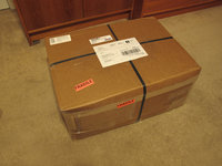 Kit1.jpg [ 273.65 KiB | Viewed 8243 times ]
The chassis, transformers and the rest of the electronic parts are all first-rate and the cabinet is a work of art.
Attachment:
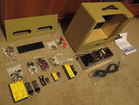 Kit6.jpg [ 361.51 KiB | Viewed 8243 times ]
The documentation that comes with the kit is excellent. There is a lot of background information as well as step by step instructions and photos for those who need them. I mainly just followed the layout drawing and the schematic. I checked the parts I received and found that everything was there.
I began by installing all the tube sockets, pots, switches and jacks on the chassis. Then I wired up the AC, the power transformer, the heaters, the output transformer secondary, the jacks and the pots.
Attachment:
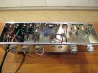 ChassisWiring001.jpg [ 466.49 KiB | Viewed 8243 times ]
Attachment:
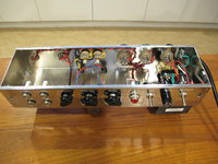 ChassisWiring002.jpg [ 456.03 KiB | Viewed 8243 times ]
Attachment:
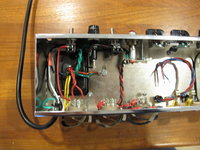 ChassisWiring004.jpg [ 440.55 KiB | Viewed 8243 times ]
Attachment:
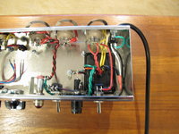 ChassisWiring005.jpg [ 458.06 KiB | Viewed 8243 times ]
Attachment:
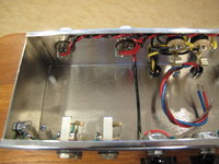 ChassisWiring006.jpg [ 426.68 KiB | Viewed 8243 times ]
Attachment:
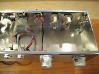 ChassisWiring007.jpg [ 411.57 KiB | Viewed 8243 times ]
Now that the power supply was wired I could give the amp its first test. No tubes were in yet, of course. I double checked all the wiring I had done so far. Then I plugged in the AC cord and flipped on the power switch. The pilot light lit up. I measured about 6.3 VAC across the heater pins at each preamp and power amp tube socket. I also checked that there was about 3.15 VAC from each heater pin to ground. I measured 5 VAC across the heater pins for the rectifier tube. I also carefully measured the high voltage coming out of the power transformer at the rectifier tube's socket. Each leg read about 350 VAC with respect to ground.
I started working on the eyelet board next. I installed all the wiring on the bottom side, then I started working from left to right installing the resistors and capacitors on the top side. I also attached all the flyoff leads using the 6" or 8" lengths recommended in the assembly manual. This turned out to be more than enough length and more than enough wire was supplied.
Once all the wires or components that go into an eyelet were in place I soldered the eyelet. Before that the wires were just passed through the eyelet and bent over to hold them in place. In the following photo you can see the second eyelet from the left at the bottom isn't soldered yet. That's where the output transformer's center tap and the B+ will connect later.
Attachment:
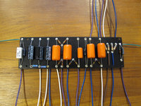 BoardTop.jpg [ 299.39 KiB | Viewed 8243 times ]
Attachment:
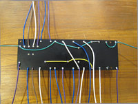 BoardBottom.jpg [ 287.5 KiB | Viewed 8243 times ]
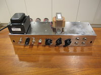
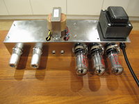
All that was left now was to attach the flyoff wires coming from the eyelet board to the tube sockets, pots and jacks.
Attachment:
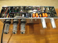 FinishedChassis001.jpg [ 550.39 KiB | Viewed 8243 times ]
Attachment:
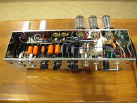 FinishedChassis002.jpg [ 557.7 KiB | Viewed 8243 times ]
The amp was now finished and ready for final testing. I checked my wiring very carefully. First visually using the layout, then I used an ohmmeter and the schematic to make sure everything that's supposed to be connected actually was connected. I did one more check to make sure there weren't any shorts and the polarity was right on all the electrolytic capacitors. All was good, so I plugged in the rectifier tube and applied power.
It passed the smoke test. It also passed all the voltage checks. I powered it down, waited for the capacitors to discharge, then I plugged in the preamp tubes. I powered it up again and they all glowed normally, there was still no smoke and all the voltages were still good.
I powered it down, waited for the capacitors to discharge, then I plugged in the power tubes and a dummy load. I applied power again. All the tubes glowed normally. There was still no smoke, no signs of red plating on the 6V6's and all the voltages were good. I powered it down again and plugged in a speaker and a guitar for the first time. I fired it up and it worked like a charm!
Attachment:
 FinishedChassis004.jpg [ 409.02 KiB | Viewed 8243 times ]
Attachment:
 FinishedChassis005.jpg [ 457.97 KiB | Viewed 8243 times ]
Mitch Markin
Port Coquitlam, BC


