scott520 wrote:
kurtlives wrote:
If all the components, design and PT values are the same as Trinity it is probably the PT voltage regulation capabilities as Stephen suggests.
Nice looking build
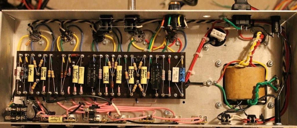
Thanks kurtlives! I've come a LONG way in my building skills, which are still meager in comparison to you guys but I'm learning! I went by the values in the layout/schematic for the Mk II pretty much dead on. The only difference is that I used a 500pf in the tone stack instead of 250pf and I didn't include the boost switch.
Is there anything I can do in the circuit to compensate for the weaker voltage regulation? The amp sounds pretty darn good now as it is so I don't want to muck around with it too much but if there's a way that I can make it more efficient then I'm all for it.
Thanks again for the input fellas!
That's a very nice looking amp you have. You even used pink wiring for the controls.

That 250pF vs. 500pF might make a tiny bit of difference actually. If you haven't before, download Duncan's Tone Stack Calculator. Its a simple interactive program that lets you play around with classic amp's tonestacks and change component values to see the affect on the frequency response. Even if you don't know how to read frequency response (Bode Plot) graphs you can at least change values and see if the graph changes visually in any appreciable manner.
I wouldn't worry about the voltages. Tubes are not super picky and have wide tolerances themselves. If you put in different tubes you would probably see your voltages change some more. If you want to play with voltages think about a VRM.