Here are pics of the tube socket wirings. First the preamp and power inverters (V1, V2, V3)
Here is V1. Notice that I used the four-tag terminals to make it easier to install the VRM coupling capacitors [and for the cascade mod that I will be installing (cascading TMB into Normal channel)]. I have not connected any wiring form the normal channel's coupling capacitor to pin 7 because that will take place with the cascade mod wiring later.
Attachment:
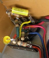 V1a.JPG [ 413.64 KiB | Viewed 7106 times ]
Attachment:
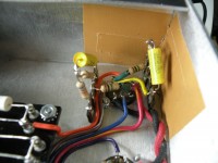 V1c.JPG [ 1.73 MiB | Viewed 7106 times ]
Here is V2
Attachment:
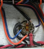 V2.JPG [ 498.55 KiB | Viewed 7106 times ]
Here is V1 and V2
Attachment:
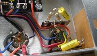 V1 V2b.JPG [ 791 KiB | Viewed 7106 times ]
Here is V3
Attachment:
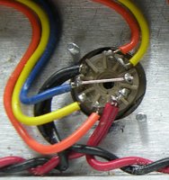 V3.JPG [ 316.32 KiB | Viewed 7106 times ]
Here is V2 and V3. I ran the boost wire (dark blueish purple) from V2 pin 3 to the 2k7 resistor, and then on to the DPDT push-pull potentiometer switch that I installed on the TMB Gain Pot. Then ran the boost wire (light blue) from the switch back to the other 2k7 resistor on the turret board. I double checked it several times to make sure that the second resistor was engaging with the push-pull switch. It works.
Attachment:
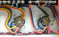 V2 V3.JPG [ 926.71 KiB | Viewed 7106 times ]
Here are V4 and V5 (the EL84 power amp tubes)
Attachment:
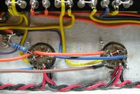 V4-V5.JPG [ 974.15 KiB | Viewed 7106 times ]
Here are V6 and V7 (the 6V6 power amp tubes)
Attachment:
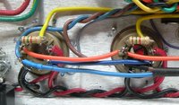 V6-V7.JPG [ 532.12 KiB | Viewed 7106 times ]
Here is a picture of most of the tubes.
Attachment:
 tubes.JPG [ 623.65 KiB | Viewed 7106 times ]
You may notice the small gray and purple cathode wires. I used 600v wire to go to the cathode switch which is a push-pull dpdt 500k potentiometer installed for the Bass pot. The cathode switch wires run from the power tubes under the board and to the potentiometer switch, then back to the turret board. I will post pics of the potentiometer side later.
Also, please excuse the cat hair in some of the pictures; it gets on everything. I have since cleaned all the sockets with alcohol and removed the dust and hair.
C2


