Okay it took me a week but i'm finally back with the rest of the photos...
First, a quick review of how I measured the impedence of the speaker:
The laptop's headphone output jack is connected to the auxilliary input jack of the home stereo amp (I kept the laptop volume low, because headphone jack output is not exactly line-level). The speaker output of the stereo amp is connected to the speaker, with a resistor Rm in series on one lead. For Rm (measurement resistor), I used a 10-Ohm, 1-Watt resistor.
The laptop is running WinISD Pro, which includes a signal generator utility. For each data point, I set the output frequency (tone) on the laptop, measured the stereo output voltage across points A-C, then measured the voltage drop across Rm, A-B. I entered these two voltages into two columns on a spreadsheet. The third column used Ohm's Law to calculate the impedence of the speaker at that frequency. I had to re-measure the stereo output voltage again for each data point, as the laptop-stereo combination was not linear throughout the frequency range of interest (not surprising at all).
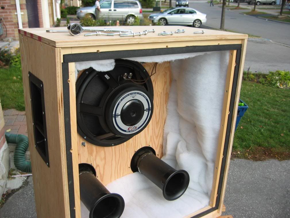
Okay, so the result of all that work was to determine that my ports were way too long. Besides some tube-cutting, I also still needed to take the box apart and glue the joints, seal them with caulk, build a brace, and some other minor clean-up. Here are the pics...
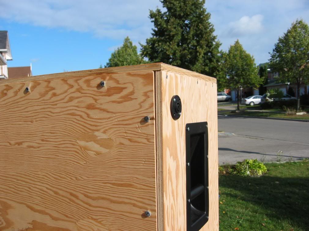
By the way, here's the back panel and the bolts that hold it on. This way, I can re-open the cab when repairs or changes are necessary - which I'm anticipating will be a lot. I know, that joint doesn't look too tight; don't worry, the battens around the back panel have weather-stripping on them (see photo, previous post). All other joints will be glued and screwed. And caulked. You can also admire the recessed steel handles (there's weather stripping under them too) and the "Speakon" connector. No quarter-inch phone jack for me! But I had to build a 1/4"-to-Speakon adaptor cable, to join my '70s amp to my 21st-century cab.

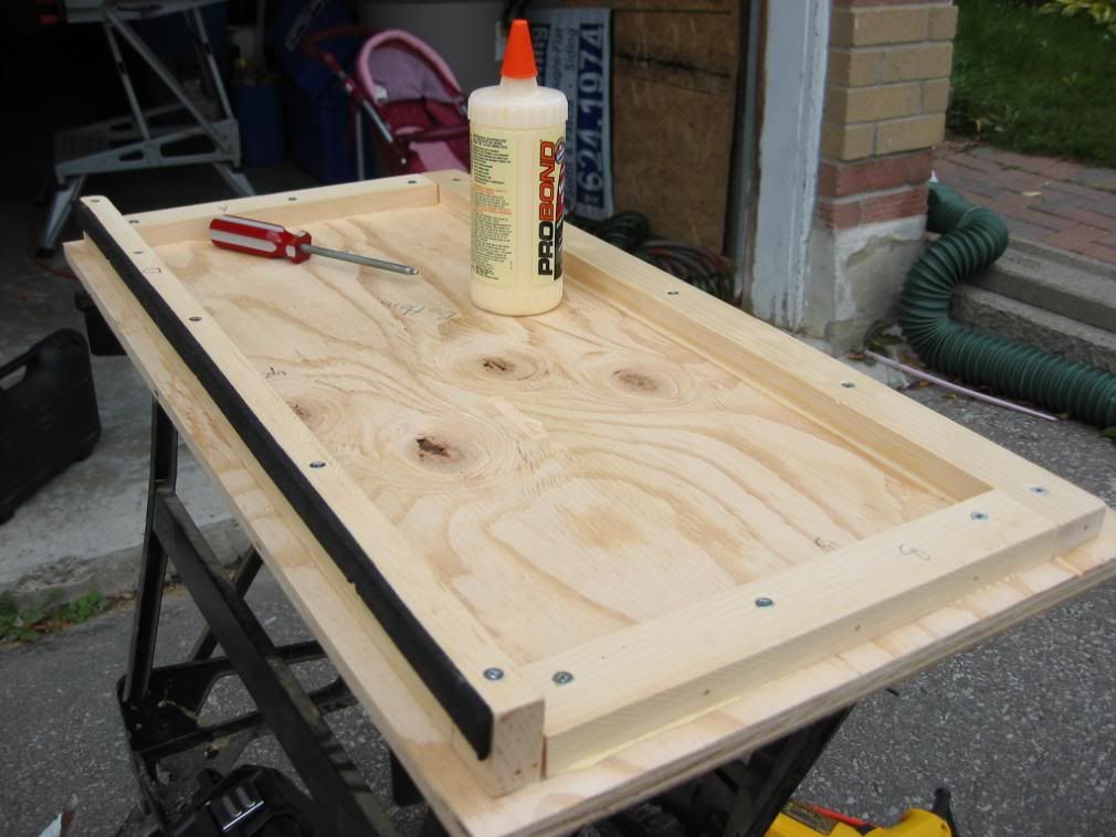
Re-assembling, with glue this time. This is the bottom panel, with battens. Only the back batten has weather-stripping on it (remember, the back is removable, so I can't caulk that joint).
Speaking of caulk, here it is! You think these beads are bad, you should see my bathroom.
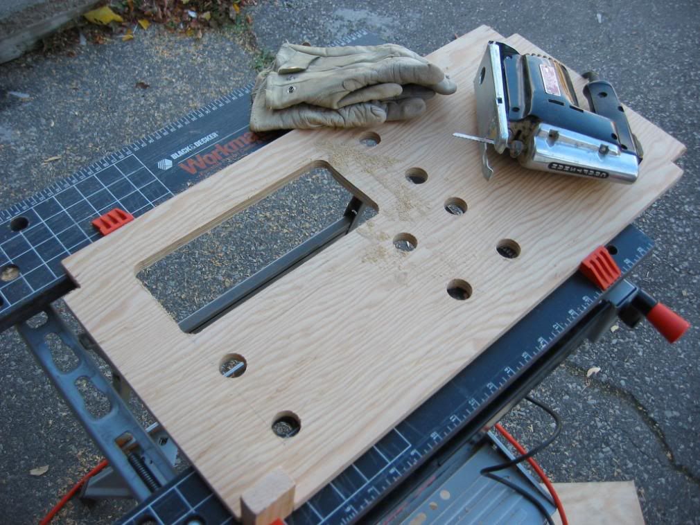
This is how you build a "shelf brace" (I'll explain what it's for in a minute). My neighbour was having an open house that day. Every time someone came to look at his house, I was on our shared driveway noisily making sawdust with some sort of power tool. Some even stopped to ask what I was building. "Giant bass speaker." Strangely, he didn't get any offers that day

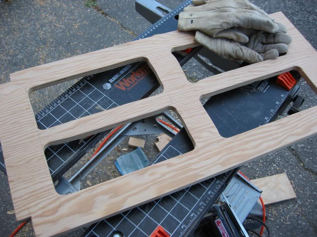
Completed shelf brace.
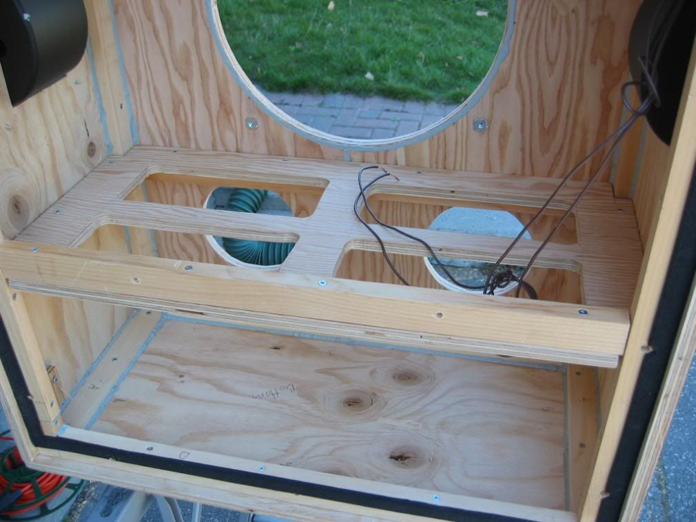
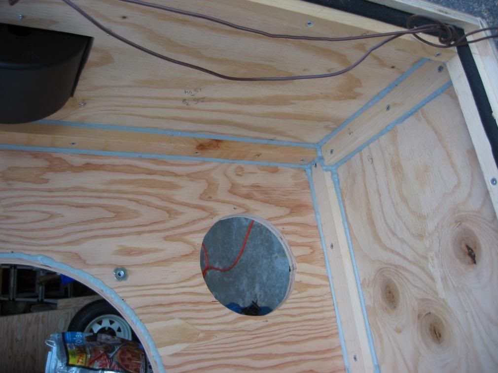
Here's the shelf brace mounted inside the cabinet. The purpose of the shelf brace is to reduce resonant vibration of the panels. A brace like this is especially good at reducing BASS resonance, because it effectively divides each panel into two smaller panels - and these smaller panels resonate at higher frequencies. This increases response and reduces distortion in the bass region. Before I added this brace, the baffle (front) would resonate a LOT, because it is the weakest panel (with all those holes cut into it), and has the 17lb speaker mounted in it.
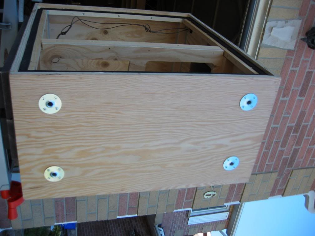
This is the bottom of the cabinet, and the sockets for the removable castors mounted therein. This cab is d@#% heavy, it needs wheels! Removable wheels, so it'll stay put while being played. I also have four rubber feet, which I'll mount after I carpet the cab.
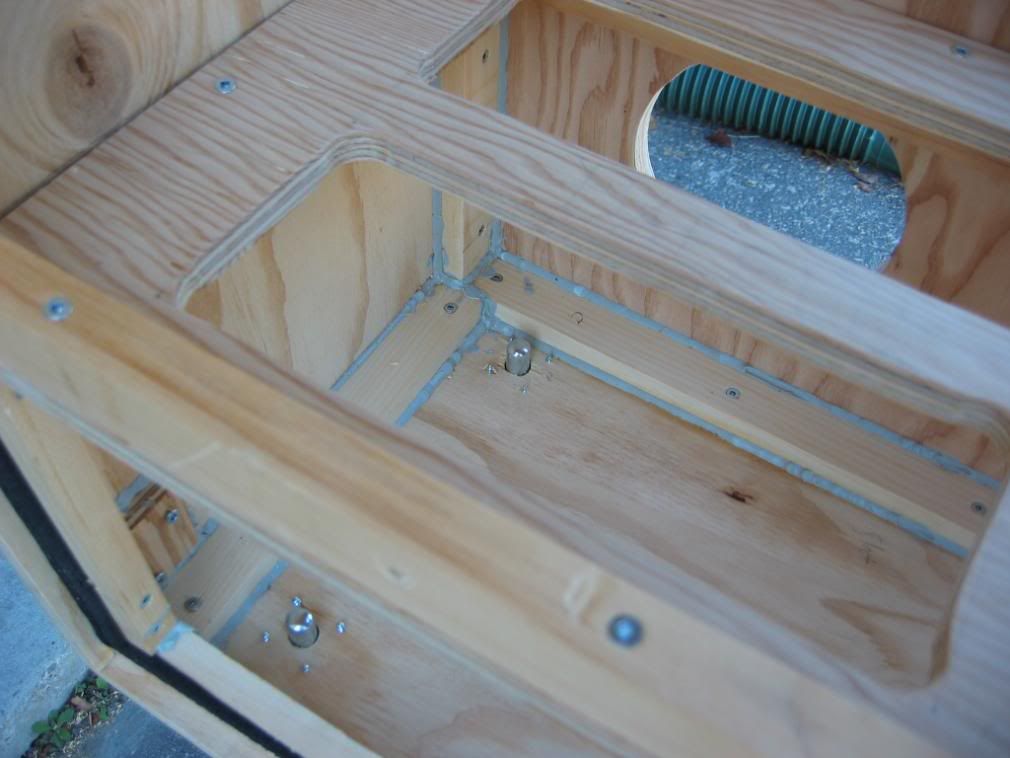
Second-last pic, here you can see the castor sockets from the inside. Yes, they're airtight... mostly.
Then I cut three inches off each port (leaving them about 7.75" long each including flared ends), remounted the speaker and ports, stapled the stuffing back in and buttoned her up. After all that work, it's disappointing that the cab looks exactly the same from the outside!
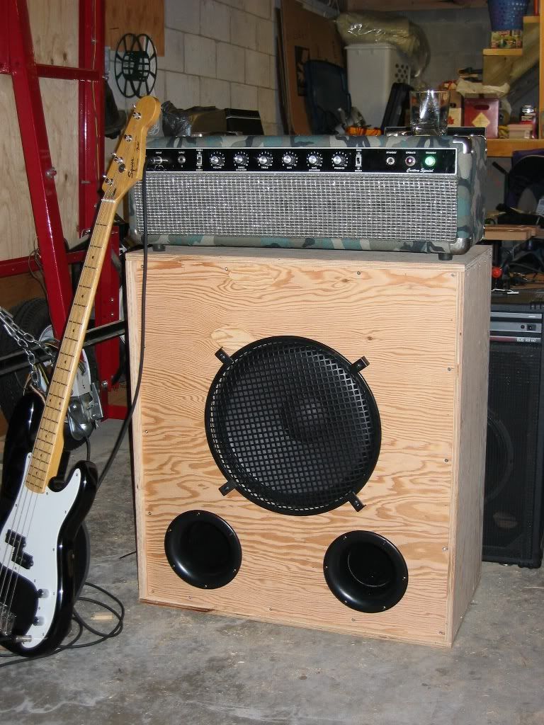
But she's solider, air-tighter, heavier

and can be wheeled about.
Now that we've seen our last warm weekend (hey, don't shoot the messenger!), it might not be til spring that I'll get around to carpetting 'er. *shrug*. I've always liked the look of bare wood. And splinters.
Oh, so I re-tested the impedence curve, and we're now at...
 32Hz!
32Hz!
Pretty close to the target 34Hz. It might be a while before I get up the motivation to crack her open one more time to cut ports and go after those last two Hz.
So that's where we are for now. Thanks for reading this far Dad, and anyone else who stuck with me. Post any questions that you have. I'll record a clip next time I'm jamming with Steve. I'd better learn 'Pulling Teeth'...