trinityamps.com

Trinity Amps Guitar Amp Forum
It is currently Tue Jul 16, 2024 10:59 am

All times are UTC - 5 hours [ DST ]


Post new topic Reply to topic  [ 95 posts ]  Go to page 1, 2, 3, 4, 5  Next
Author Message
PostPosted: Mon Feb 28, 2011 1:17 pm 
Offline
Novice
Novice

Joined: Fri Dec 17, 2010 12:18 am
Posts: 67
Thanks to everyone involeved in getting Amp Camp going and pulling it off.
I would call it a success. I do have a few things left to do to get going but for me, that was the part of the reason for attending the workshop - to learn.
I walked away with a few things to do, but I also feel that I have the knowledge and resources to get those things done on my own.

Going in to the workshop, I fully expected to have a lot more to finish on my own. When I say that, I mean that I expected to be further behind, personally.
It's just the way I am - a little laid back, I'll get to it sort of attitude. The camp ran longer than expected, but everyone hung in there.

Special thanks to Steve and Chris for their guidance through the build and for their patience.

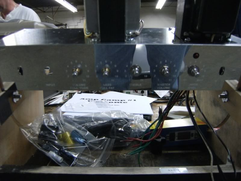
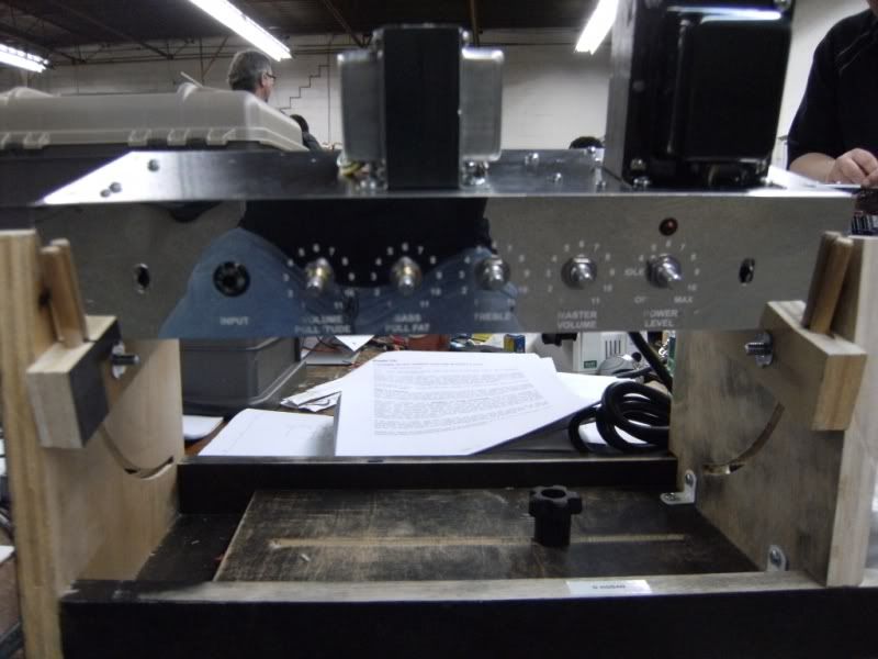
Some of the guys got things going and I think everyone was VERY impressed with what we heard. The Trinity TRAMP is an amazing amp when you consider how straight-forward it is and how flexible it is.


So, on to the pics!

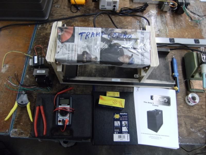
Step 1 - Pretend like you know what you're doing and look organized.

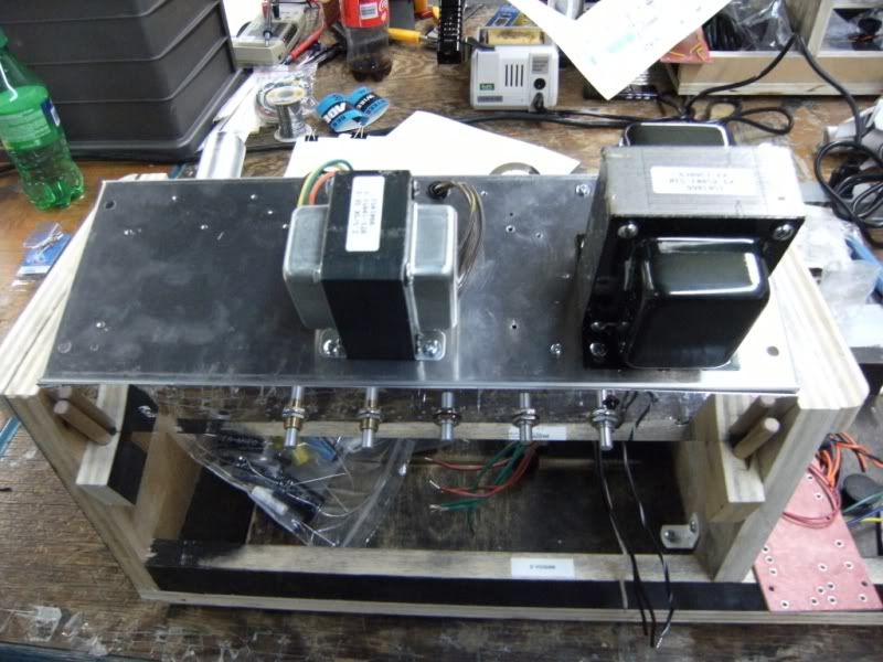
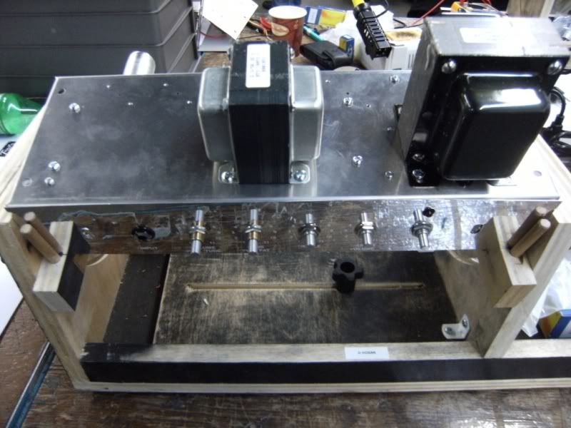
The kit was wrapped up in newspaper. The transformers sitting beside it. That guy in picture became an integral part of the tone that will make it unique to my amp. :)

Image

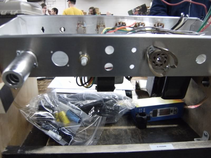
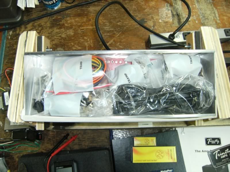
Parts - All of the parts come bagged and tagged inside the chassis.

Image

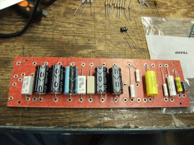
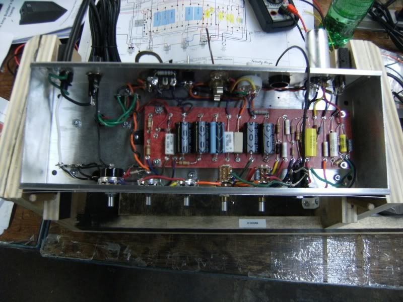
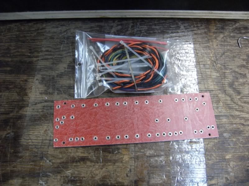
Board - The board comes with all the eyelets laid out and punched in. A big bag o' wire waits its fate.

Image

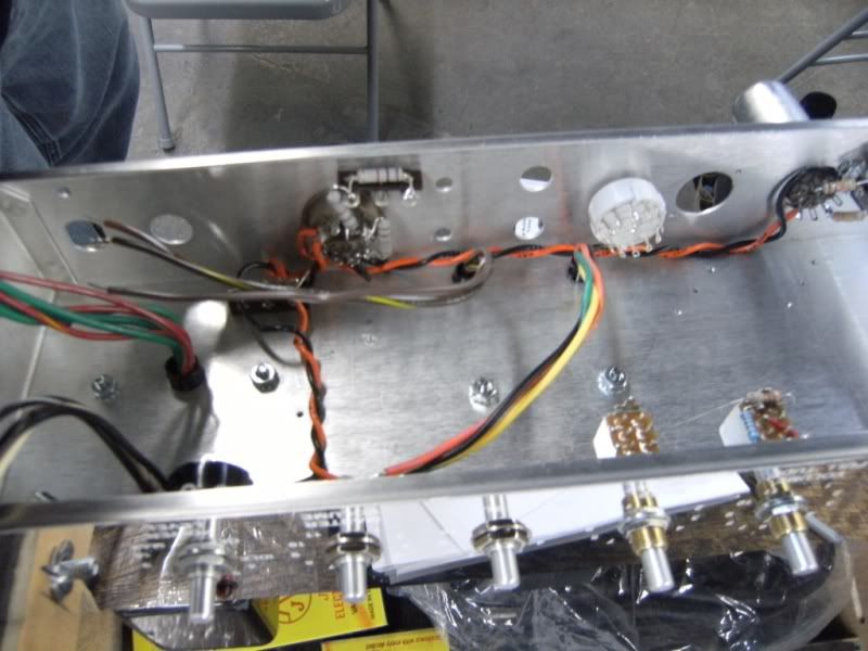
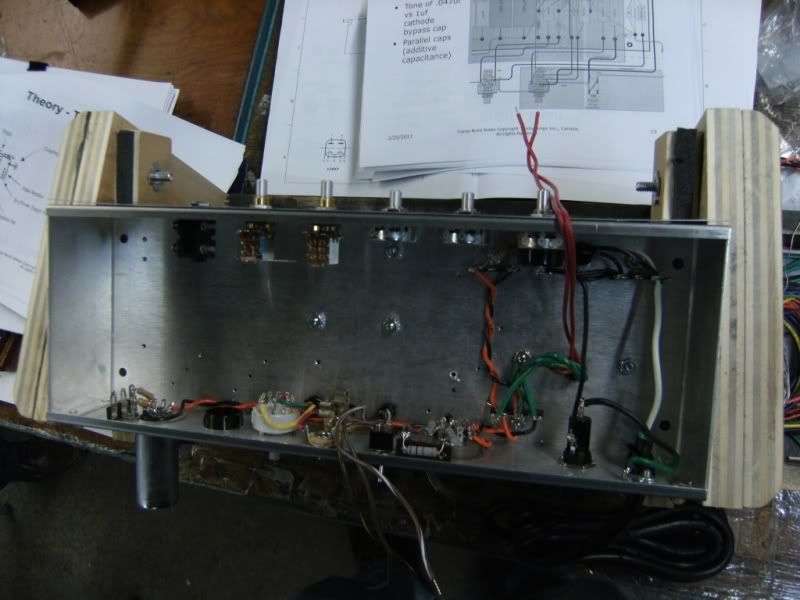
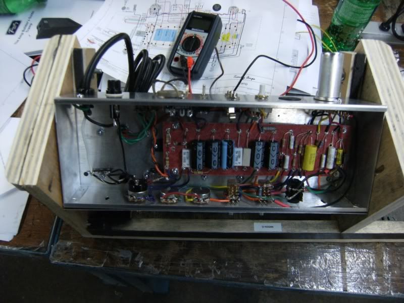
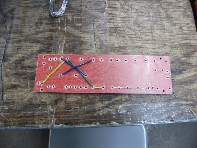
Jumpers - First thing to do is add in the jumpers wires on the bottom. Follow the layout and tack the connections into the eyelets - you'll be adding components and more leads to the same holes so leave as much room as you can but use enough solder to keep things in place.

Image

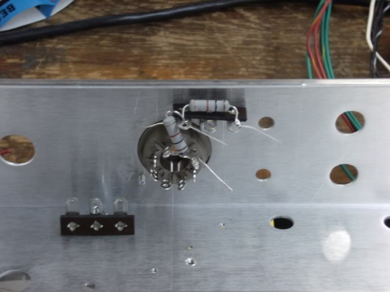
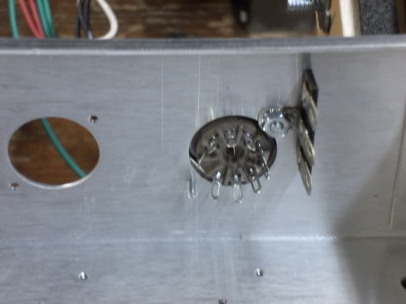
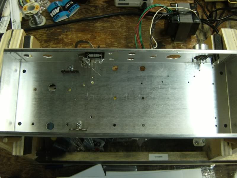
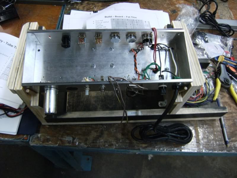
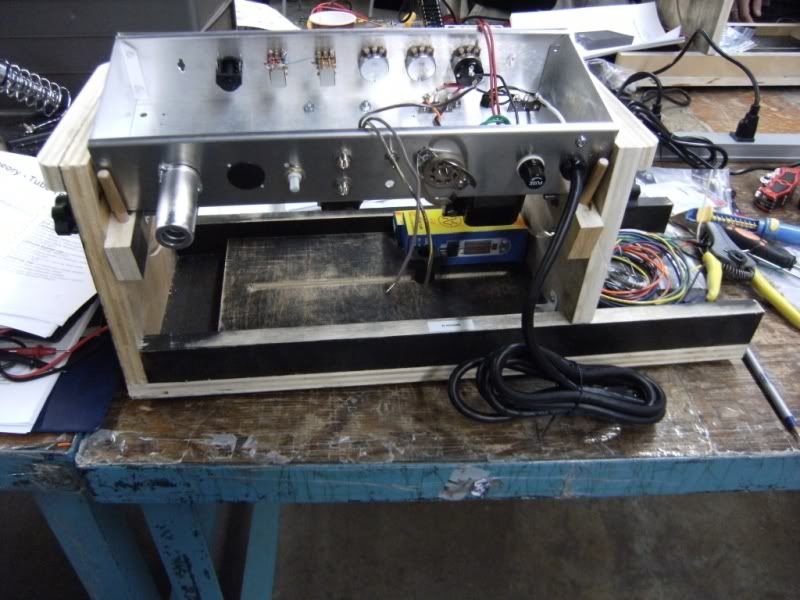
Hardware - Terminal strips and tube sockets go in. No real tricks here - except maybe to look ahead as to what else needs to go into the terminal points so that you can gauge how things should line. Try to keep leads as short as possible while leaving enough room to get new connections in place later. "Build in layers." To do that you need an idea of what all the layers are. So read the guide ahead of time.

Image

Image

Image


Last edited by dodgechargerfan on Wed Jun 29, 2011 8:18 am, edited 4 times in total.

Top
 Profile  
 
PostPosted: Mon Feb 28, 2011 1:18 pm 
Offline
Novice
Novice

Joined: Fri Dec 17, 2010 12:18 am
Posts: 67
Heater Wires and Transformers - Heater wires go in - they are the twisted orange and black wires. The other wires you see are the transformer wires coming through the grommets in the chassis.

Image

Image

Tube Sockets in place

Image

Transformers

Image

Controls -
SHINY! I have potentiometers for kneecaps!! And look! These go all the way eleven.

Image

A few shots of the progress to this point.

Image

Image


Top
 Profile  
 
PostPosted: Mon Feb 28, 2011 1:19 pm 
Offline
Novice
Novice

Joined: Fri Dec 17, 2010 12:18 am
Posts: 67
Nice cradle!! It made life a lot easier, I think. :D

Image

Populating the board - These are just in place at the moment. There's more to go on there and then they all get soldered into place. Pay attention to which eyelets will have leads going to them and be sure to leave some room in the eyelet. Just tack things in place for now. There are a couple of eyelets that are jam packed and you will likely do a little wrap around one of the component leads already there. A good solid solder joint is key everywhere but especially here.

Image

Huge leap ahead - I got carried away and forgot to take pictures. I finished populating the board and got the transformers wired in. Some of the leads to the board are in place here. nothing real tricky here. Follow the layout and solder. solder solder..

Image

Image

And pretty much finished - Last picture from Amp Camp. I'll add some more as I finish things up. I have a custom combo cabinet coming as soon as Steve gets the new shop settled in. Pics of that will follow too.

Image

Image


Top
 Profile  
 
PostPosted: Mon Feb 28, 2011 1:28 pm 
Offline
Novice
Novice

Joined: Fri Dec 17, 2010 12:18 am
Posts: 67
This is the one piece that I'm less-than-proud of in terms of my work.

I tried to keep all the leads nice and straight, but messed up the leads on the these resistors by trying to tweak and tune them too many times.

I know. It's silly, but I was doing pretty good up until that point.

This is also the "Monster" joint where many pieces come together in one eyelet. I wrapped some of the connections around the capacitor lead that was in place and it worked out well. Try and get the wrapas tight as possible for a good solid connection.


Attachments:
Ugly.jpg
Ugly.jpg [ 97.65 KiB | Viewed 18446 times ]
Top
 Profile  
 
PostPosted: Mon Feb 28, 2011 2:44 pm 
Offline
Friend
Friend

Joined: Sun Feb 13, 2011 9:15 am
Posts: 31
Location: Manitoba
Thank you for the pics. Sounds like the weekend was a success. Did anyone finish their Tramp and get to hear it?


Top
 Profile  
 
PostPosted: Mon Feb 28, 2011 3:02 pm 
Offline
Novice
Novice

Joined: Fri Dec 17, 2010 12:18 am
Posts: 67
Yep! 4 or 5, I believe.

There were a few folks still working when I left. So, maybe more.

I think everyone was impressed with the sound. At least that seemed to be the general consensus.


Top
 Profile  
 
PostPosted: Mon Feb 28, 2011 5:35 pm 
Offline

Joined: Mon Jan 03, 2011 2:24 pm
Posts: 4
mine works great. course was a lot of fun. my work on it was not up to par for myself, but my iron was giving up on me from the beginning, just happy i made it through the whole thing without any major mistakes (only some sloppy execution).

thanks chris and stephen for a great weekend. it was long, but you time was very much appreciated.


Top
 Profile  
 
PostPosted: Mon Feb 28, 2011 10:52 pm 
Offline
Holy Ghost
Holy Ghost
User avatar

Joined: Sun Mar 13, 2005 4:10 pm
Posts: 7519
Location: Canada
Nice job on the pics dodge. Thannks. Keep us posted.

_________________
Stephen
Web: www.trinityamps.com. Facebook: facebook.com/trinityamps. Twitter: @trinityamps


Top
 Profile  
 
PostPosted: Sun Mar 06, 2011 5:27 pm 
Offline
Novice
Novice

Joined: Fri Dec 17, 2010 12:18 am
Posts: 67
Okay. I'm into troubleshooting things now.

Chris checked things out before I left and gave me the go ahead - once I put in the shielded cable from the grid to the Master Volume that I completely missed. :oops:

But we checked for sound on Sunday night and didn't have anything.

I still don't.

I re-did the shielded cable running from the 330K resistor attached to pin 7.

One thing that was throwing me off when checking continuity was that when that pot is turned all the way down, it is essentially grounded, so a continuity check from the core of the coax to the chassis rings out...... until you crank the pot up. I was doing these tests with the coax disconnected from the other end.


I went back through everything and double checked voltages. Just because.
With the VRM at idle, I only saw about 39V at the + of the first 50 uF filter cap.
Cranking it up to max got me up to about 394V.
I wondered about this but read Chris's response to John's post about the same thing.

So moving on, everything else checks out: every voltage I measured is pretty close to what is shown on the layout.

Back to the issue at hand - seems to be signal only related.

I've checked as much as I can and I'm not getting any love.

I'm wanting to trace things through one leg at a time, but with the caps in the mix I guess I need a signal source and a means to measure it first.


Top
 Profile  
 
PostPosted: Sun Mar 06, 2011 7:24 pm 
Offline
Holy Ghost
Holy Ghost
User avatar

Joined: Sun Mar 13, 2005 4:10 pm
Posts: 7519
Location: Canada
Is there also about 29 volts on the cathode of the 6V6 and all the voltagees are close? If so, there is definitely a signal issue.
Normally, I go around the amp with a chopstick and see if there is a bad solder joint. Then I start at the grids of the power tube (pin 5) and VERY carefully touch it with a small insulated screwdriver to try to induce a "POP". I work back from there the the grids of the 12AX7 (pin 7 then pin 2) and try the same. When I find a point where there is not pop, I start looking there.
you can trace back on the schematic what I'm talking about and it might be more clear.

you can remove the coax cable from the input jack to board & board tothe 10K grid resistor and replace it with a solid piece. then you can be sure the coax cable is not the problem. You can repeat for all coax if you want.

_________________
Stephen
Web: www.trinityamps.com. Facebook: facebook.com/trinityamps. Twitter: @trinityamps


Top
 Profile  
 
PostPosted: Sun Mar 06, 2011 8:04 pm 
Offline
Novice
Novice

Joined: Fri Dec 17, 2010 12:18 am
Posts: 67
I double checked voltages and my cathode voltage is low - about 1.1V

I'm working on the grounds now.

Oh, when the head of the ground screw twists right off, that's too tight. :nono :rol


Top
 Profile  
 
PostPosted: Sun Mar 06, 2011 8:40 pm 
Offline
Novice
Novice

Joined: Fri Dec 17, 2010 12:18 am
Posts: 67
Hmm.

If I "eleven" everything, I see 1.3 V on pin 3 of the 12AX7
AND
I hear a little static from the speaker when I put the test lead on that pin.
If I hold the lead there, I get a little bit of a hum.

Both the static and hum are very, very quiet.

I'm going back to poke around with a wooden stick.


Top
 Profile  
 
PostPosted: Sun Mar 06, 2011 9:50 pm 
Offline
Novice
Novice

Joined: Fri Dec 17, 2010 12:18 am
Posts: 67
"Follow the noise, grasshopper."

I realized that I didn't have an instrument cable plugged in when I was testing the cathode voltage.
If I had, I would have likely tried touching the end to get a sound right after I heard the sound from touching the test leads to the test point.

So, I plugged one in, powered up, "elevened" everything and "tap, tap, tap" was heard!

I then plugged in a guitar and noodled for an hour or so. :happydance: :happydance:

One thing though - and maybe I need to read some more - I seem to have to dial things up to at least 8 to get any sound at all. It differs depending on which mode I'm in, but something be it power, master volume or volume needs to be at eight or better.
I tried two different guitars, too.

I can get good sound going, but it seems I have to "eleven" some things to get there.

I'll make more extensive notes and see if there is any kind of pattern.


Top
 Profile  
 
PostPosted: Sun Mar 06, 2011 10:31 pm 
Offline
Expert
Expert
User avatar

Joined: Sun Feb 17, 2008 4:47 pm
Posts: 960
Location: Toronto, Canada.
Nice! Sounds like your there, just about!

This may not be totally helpful now but here are all the areas you should have signal

Your voltages can be +/- 10% of what is listed on the layout/schematic so don't worry too much about that kinda stuff.


Attachments:
Tramp Signal.png
Tramp Signal.png [ 69.39 KiB | Viewed 18296 times ]

_________________
http://pdfelectronics.com
Top
 Profile  
 
PostPosted: Sun Mar 06, 2011 11:43 pm 
Offline
Holy Ghost
Holy Ghost
User avatar

Joined: Sun Mar 13, 2005 4:10 pm
Posts: 7519
Location: Canada
This is good progress. Almost there. often when this sort of thing happens, its a wrong resistor value in the chain (e.g. 220K used instead of 22K) . of course it could be a bad tube so swap 'em if you got 'em.

And what is the voltage on the 6V6 cathode (at the top of the 750 ohm , 5W resistor)?

_________________
Stephen
Web: www.trinityamps.com. Facebook: facebook.com/trinityamps. Twitter: @trinityamps


Top
 Profile  
 
PostPosted: Mon Mar 07, 2011 7:59 pm 
Offline
Novice
Novice

Joined: Fri Dec 17, 2010 12:18 am
Posts: 67
The voltage at the top of the 750 ohm, 5W resistor is about 1.3V at idle and goes up to about 20.5V at max.


Top
 Profile  
 
PostPosted: Mon Mar 07, 2011 9:16 pm 
Offline
Novice
Novice

Joined: Fri Dec 17, 2010 12:18 am
Posts: 67
I did some more checking. Nothing jumps out at me.
I re-soldered a couple of connections - but no change.

I measured these voltages at the pints indicated by the layout.
(I tried to relate them to the schematic and didn't get passed B+)


I have some monster-sized pics uploading to photobucket right now.
I'll post a link when they're up.

edit: here's the link
http://s135.photobucket.com/albums/q138 ... 11/AmpFix/

I have more, but I'm done for the night.


Attachments:
Voltages.jpg
Voltages.jpg [ 44.37 KiB | Viewed 18257 times ]
Top
 Profile  
 
PostPosted: Wed Mar 09, 2011 9:06 pm 
Offline
Novice
Novice

Joined: Fri Dec 17, 2010 12:18 am
Posts: 67
I tried a 12AT7 tube that I had in a box of tubes.
No change in terms of needing to be at 8 or higher to get any sound...

I reviewed the resistors, and I'm pretty certain I've got the right ones in the right spots.

Any other ideas?

Oh, and I know this one has been asked, but I am unsure of the correct answer.
Which way should the tube select switch be flipped?
I know that the poles that have no connections are the 6V6 side, but which direction do I flip the switch to get that setting? I've seen switches where flipping it "up" connects the center and bottom lugs and vice versa. Basically, I don't know what's happening inside the switch.

I should have done a continuity test to find that out before installing it... But I didn't. :oops:


Top
 Profile  
 
PostPosted: Wed Mar 09, 2011 10:29 pm 
Offline
Holy Ghost
Holy Ghost
User avatar

Joined: Sun Mar 13, 2005 4:10 pm
Posts: 7519
Location: Canada
The switch toggle is opposite to what the connections are. The centre ones are common and you want the two ressitors to be connected in the 6L6 position. So you can work it out from that or measure the cathode resistor value in both positions. Across the 750 it should read 750 in the 6V6 setting and less for the 6L6 setting. If the cathode voltage is around 29 it's in the right position.

We eally should have labelled those. :x

.648V on the cathode is way too low. That tube is hardly working. Resolder the parts in that chain. Check the resistor value on that cathode. Also, 200 vs 283 is suspect on that plate so check the resistor values that feed that voltage because the other plate voltage appears close.

_________________
Stephen
Web: www.trinityamps.com. Facebook: facebook.com/trinityamps. Twitter: @trinityamps


Top
 Profile  
 
PostPosted: Sat Mar 12, 2011 6:19 pm 
Offline
Novice
Novice

Joined: Fri Dec 17, 2010 12:18 am
Posts: 67
Resistors all check out.

I did find something that seemed odd, though.
I did a continuity test for the grounds and they all checked out fine.
So, I tested for shorts to ground and found that the + of the 1000uF 50V cap would give a short beep of the continuity tester and then stop.
I pulled the positive leg out and it still does it.

Bad cap bleeding some voltage to ground?


Top
 Profile  
 
Display posts from previous:  Sort by  
Post new topic Reply to topic  [ 95 posts ]  Go to page 1, 2, 3, 4, 5  Next

All times are UTC - 5 hours [ DST ]


Who is online

Users browsing this forum: No registered users and 9 guests


You cannot post new topics in this forum
You cannot reply to topics in this forum
You cannot edit your posts in this forum
You cannot delete your posts in this forum
You cannot post attachments in this forum

Search for:
Jump to:  
Powered by phpBB® Forum Software © phpBB Group