
Page 23 - Triwatt Custom Lead Amp Builder's Guide
P. 23
Assembly Steps Summary
1. Install Hardware on the Chassis.
2. Wire up the heater wires to the sockets.
3. Install Transformers on the chassis.
4. Wire up the power supply - Mains, Transformers, power switch and pilot light.
5. Assemble the turret board and Install on chassis.
6. Connect turret board leads to tubes installing off-board parts as you proceed.
7. Connect turret board leads to controls installing off-board parts as you proceed.
8. Remove input jacks. Wire with 1M film resistors and shielded cable. Re-install.
9. Check Wiring.
10. Follow Start-Up procedure.
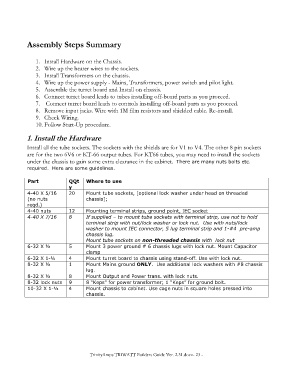
1. Install the Hardware
Install all the tube sockets. The sockets with the shields are for V1 to V4. The other 8 pin sockets
are for the two 6V6 or KT-66 output tubes. For KT66 tubes, you may need to install the sockets
under the chassis to gain some extra clearance in the cabinet. There are many nuts bolts etc.
required. Here are some guidelines.
Part QQt Where to use
y
4-40 X 5/16 20 Mount tube sockets, [optional lock washer under head on threaded
(no nuts chassis];
reqd.)
4-40 nuts 12 Mounting terminal strips, ground point, IEC socket
4-40 X 7/16 8 If supplied – to mount tube sockets with terminal strip, use nut to hold
terminal strip with nut/lock washer or lock nut. Use with nuts/lock
washer to mount IEC connector, 5 lug terminal strip and 1-#4 pre-amp
chassis lug.
Mount tube sockets on non-threaded chassis with lock nut
6-32 X ½ 5 Mount 3 power ground # 6 chassis lugs with lock nut. Mount Capacitor
clamp
6-32 X 1-¼ 4 Mount turret board to chassis using stand-off. Use with lock nut.
8-32 X ½ 1 Mount Mains ground ONLY. Use additional lock washers with #8 chassis
lug.
8-32 X ½ 8 Mount Output and Power trans. with lock nuts.
8-32 lock nuts 9 8 “Keps” for power transformer; 1 “Keps” for ground bolt.
10-32 X 1-½ 4 Mount chassis to cabinet. Use cage nuts in square holes pressed into
chassis.
TrinityAmps TRIWATT Builders Guide Ver. 2.31.docx- 23 -