
Page 26 - Triwatt Custom Lead Amp Builder's Guide
P. 26
Some components are more easily installed on other components prior to installation. Use the
following illustrations as a guideline.
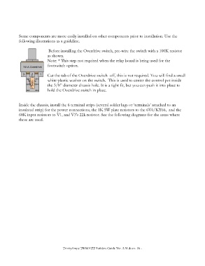
Before installing the Overdrive switch, pre-wire the switch with a 100K resistor
as shown.
Note: * This step not required when the relay board is being used for the
footswitch option.
Cut the tab of the Overdrive switch off, this is not required. You will find a small
white plastic washer on the switch. This is used to center the control pot inside
the 3/8” diameter chassis hole. It is a tight fit, but you can push it into place to
hold the Overdrive switch in place.
Inside the chassis, install the 6 terminal strips (several solder lugs or ‘terminals’ attached to an
insulated strip) for the power connections, the 1K 5W plate resistors to the 6V6/KT66, and the
68K input resistors to V1, and V3's 22k resistor. See the following diagrams for the areas where
these are used.
TrinityAmps TRIWATT Builders Guide Ver. 2.31.docx- 26 -