
Page 32 - Triwatt Custom Lead Amp Builder's Guide
P. 32
Align the High voltage leads so they are pointing towards the Power transformer. Feed the leads
through the 2 grommets installed in the chassis with the High voltage and Secondary lead going
through separate grommets. Bolt the transformer in place with the supplied 8-32 bolts & Keps
nuts. The secondary leads should be in-line with the impedance switch.
4 Power Supply Wiring
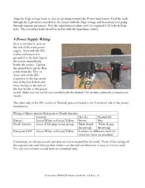
Now is the time to wire up
the rest of the main power
supply. Start with the IEC
socket and ensure it is
grounded to the bolt/lug on
the chassis immediately
beside the socket. Tighten
the ground bolt tightly. Run
a wire from the ‘Hot’ or
‘Line’ side of the IEC
connector to the lug on the
end of the fuse holder and
from the lug on the side of
the fuse holder to the power
switch. Make sure the switch was installed with the desired ‘On’ position when the connection is
‘made’.
The other side of the IEC socket or ‘Neutral’ gets connected to the ‘Common’ side of the power
transformer.
Wiring of Mains circuits: European vs North America
Ground Hot (L) Neutral (N)
Europe Green/White or Green/Yellow Brown Blue
North America Green [USA-plug round prong] Black [Small White [Large
flat prong] flat prong]
European 230V Green/White or Green/Yellow It makes no difference how the
other two wires are matched.
If necessary, tie off any unused taps that are is not required for the build. Tie it off by cutting off
the exposed wire and then put heat-shrink over the end and then tuck it away as it is not used.
You can also connect unused wires to a terminal strip.
TrinityAmps TRIWATT Builders Guide Ver. 2.31.docx- 32 -