Page 35 - Triwatt Custom Lead Amp Builder's Guide
P. 35

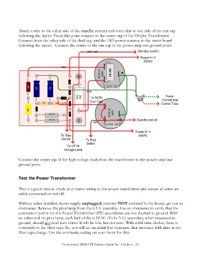
Attach a wire to the other side of the standby contact and route that to one side of the can cap
            following the layout. From this point connect to the centre tap of the Output Transformer.
            Connect from the other side of the dual cap, and the 1K5 power resistor, to the turret board
            following the layout.  Connect the centre of the can cap to the power amp star ground point.

                                                      HT1 / OT                       Standby switch
                                                                                      Power Hi V
                                                                                        350AC

                                      HT3
                                                              50-50 uF  500V  1K 5W


                      + + +   + + +
                       +       +              >|
                   82K  47uf   47uf                              220K 2W
                       50V     50V
                                              >|       HT2
                                                2K4   5W  To 50/50                                   Power
                                          >|
                                                        Can Cap                                    Transformer
                           15K     47K         >|                                                  Center Taps
                   47n  |     >|

                              910K 2W          >|                   50-50 uF  500V
                               180K 2W                                  HT1         Standby switch
                                                                  HT1
                                                                  220K 2W
                                                                                   Power Hi V
                                      To Bias                                        350AC
                                      Switch         To Bias
                                                     Switch
                                          To OT Hi
                                        Voltage Lead

            Connect the center tap of the high voltage leads from the transformer to the power amp star
            ground point.


            Test the Power Transformer


            This is a good time to check your mains wiring to the power transformer and ensure all wires are
            safely connected or tied off.

            Without tubes installed, mains supply unplugged, trannies NOT soldered to the board, get out an
            ohmmeter. Remove the pilot lamp from the 6.3 V assembly. Use an ohmmeter to verify that the
            connection points for the Power Transformer (PT) secondaries are not shorted to ground. With
            no tubes and no pilot lamp, each half of the 6.3VAC (Volts A C) secondary when measured to
            ground, should not read zero ohms. It will be low, but not zero. With solid-state diodes, there is
            continuity to the filter caps. So, you will see an initial low resistance that increases with time as the
            filter caps charge. Use the continuity setting on your meter for this.


                                       TrinityAmps TRIWATT Builders Guide Ver. 2.31.docx- 35 -
   30   31   32   33   34   35   36   37   38   39   40