
Page 39 - Triwatt Custom Lead Amp Builder's Guide
P. 39
nuts. At one end, put two screws through the chassis, install spacers, align the board holes and
install the board. Loosely tighten nuts. Repeat at other end and then tighten nuts firmly.
6 Connecting the Turret Board
Now is the time to make the connections from the turret board to the tubes.
Tip: On a copy of the layout, highlight the connections as you complete them to make sure they
are done correctly.
Also, some tube sockets require components or jumpers to be installed on them.. Some builders
prefer to do this work out of the chassis. Pre-form these components to fit into place and you
may use some heat shrink tubing make sure they do not touch other parts or pins especially the
jumper on V4. Solder the parts in place following the layout provided keeping in mind what
connections to the board still may need to be made.
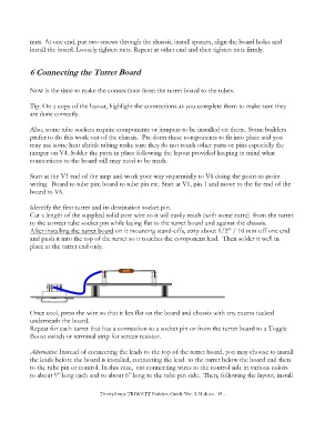
Start at the V1 end of the amp and work your way sequentially to V6 doing the point-to-point
wiring. Board to tube pin; board to tube pin etc. Start at V1, pin 1 and move to the far end of the
board to V6.
Identify the first turret and its destination socket pin.
Cut a length of the supplied solid core wire so it will easily reach (with some extra) from the turret
to the correct tube socket pin while laying flat to the turret board and against the chassis.
After installing the turret board on it mounting stand-offs, strip about 1/2” / 10 mm off one end
and push it into the top of the turret so it touches the component lead. Then solder it well in
place at the turret end only.
820R
Once cool, press the wire so that it lies flat on the board and chassis with any excess tucked
underneath the board.
Repeat for each turret that has a connection to a socket pin or from the turret board to a Toggle
Boost switch or terminal strip for screen resistor.
Alternative: Instead of connecting the leads to the top of the turret board, you may choose to install
the leads before the board is installed, connecting the lead to the turret below the board and then
to the tube pin or control. In this case, cut connecting wires to the control side in various colors
to about 9” long each and to about 6” long to the tube pin side. Then, following the layout, install
TrinityAmps TRIWATT Builders Guide Ver. 2.31.docx- 39 -