
Page 40 - Triwatt Custom Lead Amp Builder's Guide
P. 40
the connecting wires through the bottom, as described below, of the board leaving plenty of extra
length, wire is cheap, and it'll save aggravation later. Then install the board and connect to the
correct pins and control in sequence starting with V1, pin 1.
820R
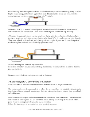
Strip about 3/4” / 15 mm off one end push it into the bottom of the turret so it touches the
component lead and bend it over. Then solder it well in place at the turret top end only.
Alternative: Some people like to run the wire from the turret to the socket pin while laying flat to
the turret board and against the chassis. Cut the wire about ½” / 10 mm longer and strip the end.
Then make a hook at the end and put it through the socket pin. Squeeze the hook with a pair of
needle nose pliers so that it is mechanically tight to the turret.
Solder it well in place. Trim off any excess wire.
Note: This procedure requires more soldering skill and may be more difficult to achieve than the
previous methods.
Do not connect the leads to the power supply or diodes yet.
7 Connecting the Turret Board to Controls
Now is the time to make the connections from the turret board to the potentiometers.
The easiest way to wire these correctly is to follow the layout, and do one terminal connection at a
time. Some of these terminals require more than one wire connection, so arrange these accordingly
and solder once.
Some controls may require components need to be installed for tone controls etc.. Pre-form these
components to fit into place and use some heat shrink tubing ensure they do not touch other
parts. Solder them in place following the layout provided.
Follow the steps above to connect wires from turrets to controls.
TrinityAmps TRIWATT Builders Guide Ver. 2.31.docx- 40 -