
Page 38 - Triwatt Custom Lead Amp Builder's Guide
P. 38
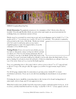
TRIWATT Completed Board Top View

            Diode Orientation: Pay particular attention to the orientation of the 5 diodes when they are
            installed.  Even though Rectifier diodes are quite robust and require no special precautions for
            soldering them, use a minimum amount of heat.

            Diodes must be connected the correct way round, and circuit diagrams may be labeled 'a' or '+' for
            anode and 'k' or '-' for cathode (yes, it really is 'k', not 'c', for cathode!).  The cathode is marked by
            a line painted on the body of the diode.  Diodes are labeled
            with their code in small print, and you may need a
            magnifying glass to read!  The diagram below shows the
            orientation of the 1N4007 diode.

            Testing Diodes: If you ever need to test a diode, you can
            test with an ohm meter, using a setting that shows a picture
            of a diode on it. Put it to that setting and just put the red
            (+ve) lead on one leg of the diode and the black lead on the
            other leg. If you get a resistance reading the cathode is on the side where the black lead is. If you
            get no reading the cathode is where the red lead is. If there is a dead short you will get a buzz tone
            out of the meter. Same as if you touched the leads together.

            Now, cut connecting wires to the control side in various colors to about 9” to 12” long each and
            to about 6” long to the tube pin side. We suggest you confirm the approximate lengths before
            cutting.

            Use 18/20 gauge stranded wire for connections to ground, power switch, B+ to output
            transformer and diodes. These can be cut-offs from installing the transformers or any provided
            wire.

            Following the layout, install the connecting wires to the bottom of the board leaving plenty of
            extra length, wire is cheap, and it'll save aggravation later.

            When the board is built, double check all components, jumpers and leads against the layout.  If all
            is correct, carefully install the board into the amp.  Locate the 4 -#6 X 1” screws, spacers and lock


                                       TrinityAmps TRIWATT Builders Guide Ver. 2.31.docx- 38 -