
Page 37 - Triwatt Custom Lead Amp Builder's Guide
P. 37
buss
2K2
+ + + + + +
+ + >|
47n | 10n | 91K 22K2W 82K 47uf 47uf
| 1n | 22n 220p 220K | 47n 1n | 50V 50V >|
1K5 47n | 2K2 1K +2uf 50V 1K | 22n + 16 uF 450V >> + 33 uF 450V >> 560K 2K2 100K 22K 100n | 7K5 2W | 100n 15K >| 2K4 5W
220K 220K | 1n 100K 100K 470R 47n | 47n | >| 47K >|
100K 100K 910K 2W
>|
220K 10K2W 100K 180K 2W
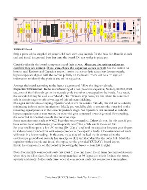
TRIWATT Board
Strip a piece of the supplied 20 gauge solid core wire long enough for the buss bar. Bend it at each
end and install the ground buss bar onto the board. Do not solder in place yet.
Carefully identify the board components and their values. Measure the resistor values to
confirm they are correct. If you can, check the capacitor values as well. See the section on
how to read Resistor and Capacitor codes. Ensure that electrolytic capacitors (power supply,
bypass caps) are aligned with the correct polarity on the board. There will be a ‘+’ sign, or
indentation to identify the positive end of the capacitor.
Arrange the board according to the layout diagram and follow the diagram closely.
Capacitor Orientation: In the manufacturing of a non-polarized capacitor, Mallory, SOZO, ETR
etc., one of the foils ends up on the outside while the other is wrapped on the inside. As a result,
the outside foil may be used as a “shield”. To minimize amp noise, we can orient the outer foil
side in circuit stages to take advantage of this inherent shielding.
If a signal travels into a coupling capacitor and enters the outside foil side, this will act as a shield,
minimizing induced noise interference. Ideally you would be able to connect the outer foil to the
incoming signal point or to the lower impedance stage. For capacitors that are used as cathode
bypass capacitors or in tone stacks, the outer foil gets connected towards ground. For coupling,
the outer foil is oriented towards the previous stage.
Some manufacturers such as SOZO have this polarity marked. Others do not. In this case, if you
have access to an oscilloscope, you can quickly determine which lead is the outer foil.
Set your oscilloscope to a low AC setting [10 - 20mV] and hold the capacitor between your fingers
to induce noise. Connect the oscilloscope probes to the capacitor leads. One orientation of leads
will result in a lower reading. In this case, make note of the lead that is connected to the
oscilloscope ground lead (usually has an alligator clip) and that identifies the outer foil. Mark the
capacitor with a sharpie and install the cap as per the provided TRIWATT board layout.
Install the components on the board by following the layout – from left to right.
Note: For multiple component leads that must fit into one turret, insert them first and solder once
when they are all in place. Bend each component lead at 90 degrees so that it fits into the turret,
squarely and neatly. Solder each turret once all component leads that connect to it are in place.
TrinityAmps TRIWATT Builders Guide Ver. 2.31.docx- 37 -